background image

8

MN1617

A5

Unit Size

Reduction Stage

Pints

Liters

38

2

2.5

1.2

3

2.5

1.2

48

2

3.8

1.8

3

3.8

1.8

58

2

5.9

2.8

3

5.5

2.6

68

2

8.0

3.8

3

7.8

3.7

88

2

16.9

8.0

3

16.3

7.7

108

2

25.4

12.0

3

24.7

11.7

128

2

45.6

21.6

3

45.0

21.3

148

2

67.0

31.7

3

65.9

31.2

168

2

104.0

49.2

3

102.3

48.4

A5

Unit 

Size

Reduction 

Stage

Input 

Reducer 

Pints

Input 

Reducer 

Liters

Primary 

Reducer 

Pints

Primary 

Reducer 

Liters

68

4

0.5

0.3

9.9

4.7

5

1.3

0.6

9.9

4.7

88

4

1.2

0.6

21.6

10.2

5

3.4

1.6

21.6

10.2

108

4

1.2

0.6

33.3

15.8

5

3.4

1.6

33.3

15.8

128

4

2.1

1.0

54.8

25.9

5

3.4

1.6

54.8

25.9

148

4

2.1

1.0

83.5

39.5

5

3.4

1.6

83.5

39.5

168

4

2.1

1.0

122.4

57.9

5

5.7

2.7

122.4

57.9

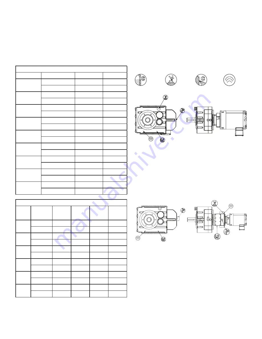
Motorized Shaft Mount (MSM) Reducers and Integral Gearmotors

These mounting arrangements are for all output configurations and output shaft types.
IMPORTANT: When ordering, please specify mounting position for correct oil quantity. In cases of mounting position other than 

shown here with regard to the oil quantity, please reference the Incline Mounting page in the Quantis Engineering Catalog, and contact 

Application Engineering.

NOTE: The oil volumes shown are approximate values and cannot be used to correctly set the reducer oil level. ALWAYS fill 

the reducer to the correct oil level plug and recheck in 1 week.

A5 – Horizontal – Wall Mount

Oil Level

Ventilation

Oil Drain

Sensor

NOTES:

All MSM 38 units are sealed for life and furnished with only one plug for filling and draining.

4 and 5 stage reduction reducer consists of two reducers assembled to each other, the Input Reducer and the Primary Reducer. The reducers are 

sealed from each other and require different oil levels per the chart.

* Hole location on opposite side of reducer.

*

A

*

*

A

*

REQUIRES

PIPE

EXTENSION

*

Содержание Quantis MSM

Страница 1: ...struction manuals must be followed Inspections should be made as necessary to assure safe operation under prevailing conditions Proper guards and other suitable safety devices or procedures as may be...

Страница 2: ...re greasing and 5 pumps of grease for subsequent re greasing Dodge Quantis MSM Reducers are shipped with filling oil level and drain plugs in place A separate breather is included with the unit Befor...

Страница 3: ...to 105 F 12 C to 41 C Mineral Oil 220 Mobilgear 600 XP 220 standard factory fill 20 F to 50 F 29 C to 13 C Synthetic Oil 68 Mobil SHC 626 10 F to 115 F 23 C to 46 C Synthetic Oil 220 Mobil SHC 630 30...

Страница 4: ...aft types IMPORTANT When ordering please specify mounting position for correct oil quantity In cases of mounting position other than shown here with regard to the oil quantity please reference the Inc...

Страница 5: ...with regard to the oil quantity please reference the Incline Mounting page in the Quantis Engineering Catalog and contact Application Engineering NOTE The oil volumes shown are approximate values and...

Страница 6: ...all output configurations and output shaft types IMPORTANT When ordering please specify mounting position for correct oil quantity In cases of mounting position other than shown here with regard to th...

Страница 7: ...nting position for correct oil quantity In cases of mounting position other than shown here with regard to the oil quantity please reference the Incline Mounting page in the Quantis Engineering Catalo...

Страница 8: ...output configurations and output shaft types IMPORTANT When ordering please specify mounting position for correct oil quantity In cases of mounting position other than shown here with regard to the oi...

Страница 9: ...utput configurations and output shaft types IMPORTANT When ordering please specify mounting position for correct oil quantity In cases of mounting position other than shown here with regard to the oil...

Страница 10: ...g position used Review the data plates on the reducer and drive motor to verify that the drive is correct for the intended loads speeds and power supply The gear reducer should be installed in a locat...

Страница 11: ...collar Install the clamp collar onto the reducer input shaft and line up the mark previously made on the clamp collar with the center of the keyway in the shaft If the clamp collar rotates freely tig...

Страница 12: ...lb in 180Nm 160 180 200 M16 1593lb in 180Nm For 3 Piece Coupled Input Reducers Reference Figure 1 For Clamp Collar Input Reducers Reference Figure 2 NEMA Motor Frame Coupling Size Setscrew Size Setscr...

Страница 13: ...ize onto the customer shaft before installing reducer onto the shaft The gearbox is pulled onto the shaft by means of a threaded rod and nut assembly as shown in Figure 4 below The threaded rod and sp...

Страница 14: ...4375 M_108 0 50 1 75 1 00 0 31 3 4 10 7 8 14 3 66 0 81 2 375 0 625 2 370 2 375 0 000 0 0007 2 65 7 25 3 00 12 50 8 19 2 875 2 4375 2 433 2 438 0 000 0 0007 2 714 2 9375 M_128 0 50 2 00 1 00 0 31 3 4...

Страница 15: ...5 80 320 208 72 70 20 69 9 70 0 0000 0 0019 74 82 M_128 12 52 24 10 M20 M20x1 5 123 16 70 20 69 9 70 0 0000 0 0019 74 240 80 360 263 82 80 22 79 9 80 0 000 0 019 85 85 92 M_148 7 61 24 10 M20 M20x1 5...

Страница 16: ...ULATE B4 4 5 6 9 8 7 1 2 3 L1 L2 L3 B1 B5 INSULATE B3 INSULATE B4 B2 1 2 3 9 8 7 4 5 6 L1 L2 L3 4 5 6 9 8 7 1 2 3 L1 L2 L3 B3 B5 INSULATE B4 SEPARATE SINGLE PHASE LINE TO BRAKE B1 B5 INSULATE B3 INSUL...

Отзывы: