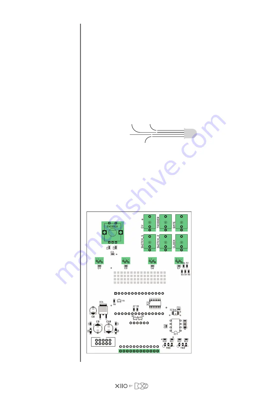
Insert jacks, addressable LEDs, encoder and the included 12 pin header into PCB.
Don't solder them yet!
To line up the encoder with jacks mount an extra nut and washer on its thread.
This will narrow the gap between the encoder body and panel.
Make sure you've got the correct LEDs (two long and two short legs).
The sources in the BOM are tested. An eBay seller used to sell classic
common anode RGB leds as addressable. If you are not sure, please test your LEDs.
Apply +5V through a 100R resistor to the inner short leg, and connect
the inner long leg to ground. Blue light means you've got the correct LEDs,
green means classic common anode RGB leds (not good for you).
Slide front panel onto the jacks and encoder, finger tighten nuts of jacks and encoder,
check alignment, and solder them (jacks and encoder). Make sure the SMD header
is standing on it's place, solder female part to PCB and the outer six pins to the panel,
which are facing the bottom of the module.
Slide LEDs to their places, realign them to same height, solder them. Now remove
the panel, pay attention to the 12 pin header, pull it apart gently, not to rip off the pads
and traces from the back of the panel. Solder the remaining six pins of the SMD connector.
STEP 5
PAGE: 04
DATA IN
+5V
GND
DATA OUT


