


I
NSTRUCTION
&
P
ARTS
M
ANUAL
Pag.
35
Edition A
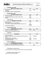
16.2.
P
ROBLEMS
Problems
Reasons
How to solve the problem
Twisted cut
Feed rate
Blade is not perpendicular
Reduce the feed rate
Register the blade
The blade looses the sharpness
quickly
The blade vibrates
Cutting speed
Wrong teeth
The blade slides on the material
Feed rate
Reduce the speed
Use a blade with the right teeth
Increase the feed rate
Increase the band tension
Blade teeth break
Feed rate
Wrong teeth
Cutting speed
The cut begins on an irregular or thin section
Material unclamped
Reduce the feed rate
Use a blade with the right teeth
Reduce the speed
Turn the material on the machine
Clamp the material
Blade breaks
The guides don’t work properly
Blade in tension even when work is over
Wrong weldment
Blade installed incorrectly
Check the guides and their carbide inserts
Remove tension when not working
Return the blade to the supplier
Check the blade
Stripes on a side of the blade
Only one guide guides the blade
Regulate the guides
Blade stalls
Feed rate
Reduce the feed rate
The motors are off
Problems with the electric source
Wrong circuit breakers
Short circuit
Look for the problem and solve it
16.3.
B
LADE REPLACEMENT
1.
Raise completely the saw head.
2.
Wear protection gloves.
3.
Rotate the band tension wheel CW, so to release tension; (or work on the band tension handle for machines
equipped with hydraulic band tension).
4.
Stop the hydraulic power unit and switch the machine off, putting it under “out of service” status.
5.
Open both the band wheel doors, and secure them;
6.
If stalling in a bar, remove the blade slowly;
7.
It is suggested to cover the blade using the plastic teeth strip that was originally on the blade;
8.
Take the old blade in a place where no one can be injured;
9.
Clean using compressed air the wheel tracks and the band guides;
10.
Put the new blade on the wheel paying
ATTENTION TO THE CUTTING DIRECTION
;
11.
Make sure the blade sits completely on the wheel track;
12.
Place the blade in the guide arms;
13.
Tension the blade making sure it sits correctly on the track..
14.
Remove, with the blade off, the tooth cap protection;
15.
Close the doors and start the machine again.