background image

Digital Monitoring Products  |  XTLtouch Installation Guide

6

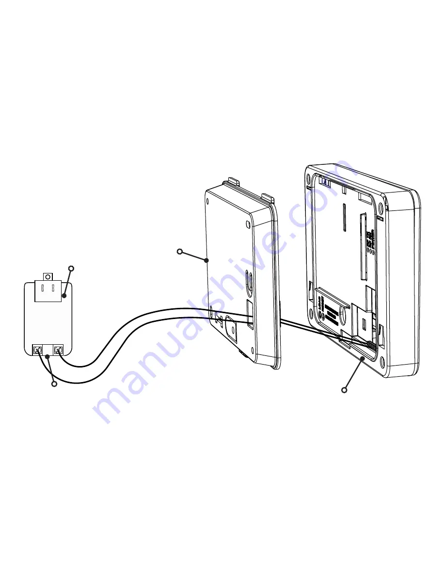
- 12V +

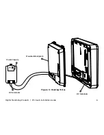
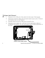
Figure 5: Routing Wires 

Power Supply

Mounted Backplate

DC terminals

DC terminals

Содержание XTLtouch Series

Страница 1: ...XTLtouchTM Series Installation Guide...

Страница 2: ......

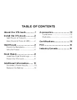
Страница 3: ...d XTLtouchUSB 2 Wall Mount 3 Mount the Backplate 3 Wire for Power 5 Desk Stand 8 Install the Desk Stand Legs 8 Power the XTLtouch 9 Additional Information 10 Secondary Power Supply 10 Replace the Batt...

Страница 4: ...as an LTE cellular communicator pre installed for cellular use The XTLtouch can be mounted to a wall or can be used for tabletop use The XTLtouch provides the following features 5 graphic touchscreen...

Страница 5: ...to a wall Note Install the XTLtouch near a wall outlet for the plug in power supply The power supply should be located within 100 feet of the XTLtouch using 22 AWG wire Desk Stand XTLtouchUSB For des...

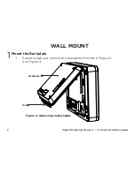
Страница 6: ...tal Monitoring Products XTLtouch Installation Guide 3 WALL MOUNT Mount the Backplate 1 Press the tab and remove the backplate from the XTLtouch See Figure 3 1 Figure 3 Removing the Backplate Backplate...

Страница 7: ...Monitoring Products XTLtouch Installation Guide 4 2 Use the level and the included 6 screws to mount the backplate to the wall See Figure 4 for mounting hole locations Figure 4 Mounting Hole Location...

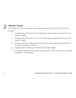
Страница 8: ...DC terminal to the positive terminal on the power supply 2 Connect the XTLtouch DC terminal to the negative terminal on the power supply 3 Plug the power supply into a 120 VAC 60 Hz dedicated outlet t...

Страница 9: ...Digital Monitoring Products XTLtouch Installation Guide 6 12V Figure 5 Routing Wires Power Supply Mounted Backplate DC terminals DC terminals...

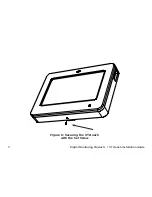
Страница 10: ...Digital Monitoring Products XTLtouch Installation Guide 7 Figure 6 Securing the XTLtouch with the Set Screw...

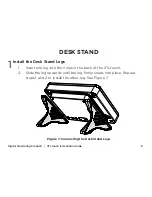
Страница 11: ...SK STAND Install the Desk Stand Legs 1 Insert one leg into the holes in the back of the XTLtouch 2 Slide the leg upwards until the leg firmly snaps into place Repeat steps 1 and 2 to install the other...

Страница 12: ...esired insert the cable into the strain relief to secure the XTLtouch to its power source See Figure 8 3 Plug the other end of the cable into the transformer 4 Plug the power supply into a 120 VAC 60...

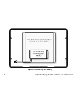
Страница 13: ...hould not operate the panel on a daily basis If the battery is low or not plugged into the battery connector a low battery condition is indicated by the panel If a 24 hour standby battery is needed co...

Страница 14: ...Digital Monitoring Products XTLtouch Installation Guide 11 3 8 V 4800 mAh Rechargeable Battery required for 24 hour standby 3 8 V 800 mAh Rechargeable Battery Figure 9 Replacing the Battery...

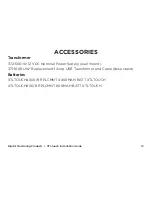
Страница 15: ...n Guide 12 ACCESSORIES Transformer 372 500 W 12 VDC Nominal Power Supply wall mount 371 1000U W Replacement 1 Amp USB Transformer and Cable desk stand Batteries XTLTOUCH4800 8 RPLCMNT 4800MAH BATT XTL...

Страница 16: ...C0199 IC 5251A PC0199 FCC Wi Fi Network Approvals FCC ID VW4 ATWINC1500 IC 20266 WINC1500PB FCC LTE Cellular Communicators LTE FCC Part 15 ID R17ME910C1NV Intertek ETL Listed ANSI UL 985 Household Fir...

Страница 17: ...to comply with the limits for a Class B digital device pursuant to part 15 of the FCC Rules These limits are designed to provide reasonable protection against harmful interference in a residential ins...

Страница 18: ...nd receiver Connect the equipment into an outlet on a circuit different from that to which the receiver is connected Consult the dealer or an experienced radio TV technician for help Note For listed r...

Страница 19: ...nce including interference that may cause undesired operation of the device Le pr sent appareil est conforme aux CNR d Industrie Canada applicables aux appareils radio exempts de licence L exploitatio...

Страница 20: ...LT 1788 18373 2018 Digital Monitoring Products Inc...

Отзывы: