


XR150/XR550 Series Canadian Installation Guide
Digital Monitoring Products
19
INSTALLATION
to determine if panel is seizing the line:
1. Unplug phone cord from RJ31X
2. Place butt-set on pins 4 and 5
3. Listen for dial tone. With dial tone present, lift either wire from pins 1 or 8
4. Listen for dial tone again. If the dial tone is present, RJ31X wiring is correct. If no dial tone is present, the
RJ31X wiring is backwards. Rewire so dial tone is coming IN on 4 and 5.
If you still have trouble with the phone line, you may need to replace the RJ cord. If the dial tone is still not
present, swap out the RJ31X phone block.
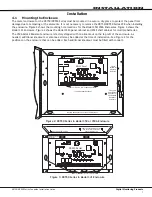
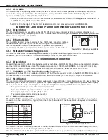
Reset and Tamper Headers
18.1 J16 Reset Header
The reset header is located just above the terminal strip on the right side of
the circuit board and is used to reset the XR150/XR550 Series microprocessor.
To reset the panel when first installing the system, install the reset jumper
before applying power to the panel. After connecting the AC and battery,
remove the reset jumper.
To reset the panel while the system is operational, for example, prior to
reprogramming, install the reset jumper without powering down the system.
Remove the reset jumper after one or two seconds.
After resetting the panel, begin programming within 30 minutes. If you wait
longer than 30 minutes, you must reset the panel again.
18.2 J4 Tamper Header
The TAMPER header is for use with the optional DMP 306 Tamper Harness. The
harness connects to one or more tamper switches mounted inside the panel
enclosure to supervise against unauthorized enclosure opening or removal.
Refer to the wiring diagram on the enclosure door for correct tamper switch
wiring.
How the Tamper Works
If the enclosure is opened or removed while one or more of the system areas
are armed, a panel tamper alarm is indicated. If all areas are disarmed, a
panel tamper trouble is indicated.
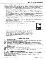
Cellular Modules
19.1 J24 Header
The J24 header is located to the right of the J7 Expansion Module on the right side of the circuit board and is
used to connect the DMP Model 263HCAN HSPA+ Cellular Communicator. This provides a fully supervised alarm
communication path for the XR150/XR550 Canadian panel. Refer to the 263HCAN (LT-1270) Installation Sheet for
complete information.
19.2 Module Installation
1.
Insert the PCB standoff end with flanges into the standoff hole in the panel PCB.
2. Align the PCB standoff with the standoff hole in the module PCB.
3. Press the module PCB card 12 pin connector onto the Cell Module (J24) connector on the panel while applying
even pressure to both sides of the board to fully seat the module. See Figure 13.
Note:
If needed, the PCB can be removed from the enclosure to allow placement of the cell module.
19.3 Connecting the Antenna
1. Attach a 381 cable to the SMA connector on the cell module.
2. Position one of the supplied washers onto the other end of the 381 SMA connector and push the threaded end
through an enclosure knockout.
3. Position the second washer onto the threaded end extending through the knockout and secure the nut.
4. Attach the included 383 Antenna to the SMA connector. See Figure 13.
Note:
As an alternative, an antenna coax
can be connected directly to the cell module SMA connector when the coax enters the enclosure via conduit.
Momentarily place the Reset
jumper over both of the J16
pins to reset the panel.
K
J6
J23
Figure 12: XR550 Series
Canadian Panel Showing the
Reset Jumper


