


7760 Keypad Installation Guide
Digital Monitoring Products
3
Keypad Bus Monitor
For Fire Protective systems, the 893/893A Module must be installed in the XR500 Series or XR200 control panel to
monitor the keypad bus and sound an audible trouble whenever the keypad bus fails to operate. Refer to the 893/
893A Module Installation Sheet (LT‑0135).
Touchscreen Display
The 7760 is an integrated LCD with a touchscreen user interface that can be programmed to turn off (clear glass)
during periods when the keypad is not in use. See Backlighting Brightness under End‑User Options. Touch the area
over each key, icon, or other selection to operate the keypad.
Warning
: DO NOT use any sharp objects to operate the touchscreen such as a pen or pencil.
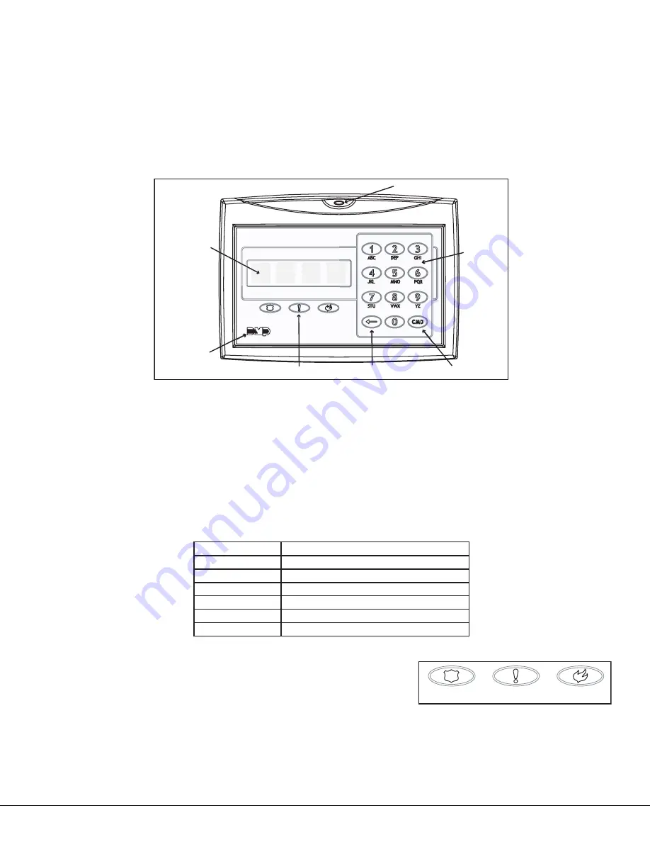
aC power/armed Led
three panic icons (Optional)
32-Character
display with
Four touch
Select areas
data entry
Keyboard
COMMand Key
back arrow Key
Logo
Figure 4: 7760 LCD Glass Keypad
Keypad Backlighting
The touchscreen illuminates at full brightness any time the glass is touched. When the speaker is sounding, the
backlight illuminates at one‑half (1/2) brightness. During an alarm condition, the backlight turns Red. When all
alarm conditions are cleared from the display, the Red backlight returns to Blue and the user‑selected brightness.
This user selected brightness may be set to off which allows the glass graphic display to turn off (clear glass).
Simply touch the glass anywhere and the backlight illuminates for data entry.
AC Power/Armed LED Operation
The LED indicates the Power and Armed status of the panel. Depending on the operation, the LED displays in Red or
Blue as listed in the table.
Color and Activity Operation
Blue Steady
Panel Disarmed, AC Power OK, Battery OK
Blue Blinking
Panel Disarmed, AC Power OK, Battery Fault
No Light
Panel Disarmed, AC Power Fault, Battery OK
Red Steady
Panel Armed, AC Power OK, Battery OK
Red/Blue Alternate
Panel Armed, AC Power OK, Battery Fault
Red Blinking
Panel Armed, AC Power Fault, Battery OK
Panic Icons
All 7760 keypads offer an optional Panic function that allows users to send
Panic, Emergency, or Fire reports to the central station. You must enable
the Panic function in Installer Options in order to use the Panic Icons. See
Programming Keypad Options later in this document. The Panic Icons are
shown in Figure 5.
The user must touch and hold the Icon for two seconds until a beep from the keypad is heard. At the beep, the
panel sends the following zone alarm reports to the central station:
Panic
(Police Icon) ‑ Zone 19 + Device Address
Emergency -
non‑medical (Exclamation Point Icon) ‑ Zone 29 + Device Address
Fire
(Flame Icon) ‑ Zone 39 + Device Address
Figure 5: Panic Icons
Police
Emergency
Fire


