22
©2014 DJI. All Rights Reserved.
Appendix
Attention
For safety reasons, please pay serious attention to all of the following items:
To avoid motor damage ensure nothing blocks the servo drive module’s total range of movement.
Before powering on, spin the gimbal by hand through the complete rotational axes to ensure
nothing is blocking the mechanical movement of the gimbal.
Be sure to mount the side of servo drive module1 with ports facing towards the aircraft tail.
The gimbal’s center of gravity balance has been preset. The gimbal balance is directly correlated
with the gimbal performance. Please do not adjust the gimbal’s center of gravity by yourself.
The gimbal is a sophisticated device. Do not remove any other screws from the gimbal which may
result in poor performance or even damage.
Do not unplug any cables attached to the gimbal ports or change the mechanical structure.
Make sure all wiring is correct, otherwise it may lead to abnormal operation or the gimbal may not
operate efficiently.
Make sure to connect the wireless video transmission module to the GCU prior to powering on the
system.
The factory AV video power cable is recommended.
Make sure you solder the AV video power cable to the wireless video transmission module
correctly. Ensure the cables are insulated and protected to prevent and type of short circuit.
Pay close attention to the voltage of S800 EVO/S1000 and be sure it is within the defined limits (6S)
when using one battery for both the S800 EVO/S1000 and power supply for the gimbal.
Prevent the gimbal from ever touching the contact points of a power cable; otherwise it may lead
to a short circuit of the gimbal, resulting in complete failure.
Before powering on, adjust the roll axis of the gimbal to be level when the camera is attached.
1-Pilot Solution
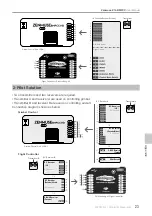
This is an example of the wiring configuration. Prepare one 14-channel Transmitter/RC receiver
for the aircraft and gimbal control.
Setup the Aileron, Elevator, Throttle, and Rudder channels on Transmitter for the aircraft’s roll,
elevator, throttle, and rudder control. Also connect the Transmitter’s AUX2 for aircraft control
modes (Please refer to the Flight Control System User Manual).
Choose three 3-position switches for gimbal’s ROLL, TILT, and PAN rotation control. The switch at
center position is 0 velocity and at the end point position is at maximum velocity.
Choose one 3-position switch/channel as the gimbal’s Working Modes switch (MODE).
Choose one 2-position switch/channel as the camera record control switch (AUX3).
Choose one 3-position switch/channel as the camera aperture control switch (AUX1).
Connect the receiver to GCU and Flight Control System MC correctly.
Appendix
Содержание Zenmuse Z15-BMPCC
Страница 1: ...Zenmuse Z15 BMPCC 2014 05 V1 0 User Manual ...
Страница 27: ......


