background image

12

DIXON INDUSTRIES, INC.

a BLOUNT company

Airport Industrial Park

P.O. Box 1569

Coffeyville, Ks 67337- 0945

620-251-2000

Fax 620-251-4117

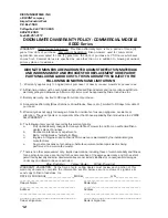
DIXON LIMITED WARRANTY POLICY - COMMERCIAL MODELS

8000 Series

WARRANTY:  Home Owner Application:  This Dixon Warranty term is for a period of three (3)

years from date of purchase.  Commercial Application: Dixon mowers used for commercial

application are warranted for one (1) year from the date of purchase or 750 hours whichever

comes first.  Commercial use is specified as use other than, or in addition to, mowing at owner’s

primary place of residence.

DIXON ZTR MOWERS ARE WARRANTED AGAINST DEFECTS IN MATERIALS

AND WORKMANSHIP AND PROVIDES FOR REPLACEMENT OR REPAIR OF

PARTS INCLUDING LABOR COSTS.  THIS WARRANTY IS SUBJECT TO THE

FOLLOWING CONDITIONS AND LIMITATIONS:

1.  Warranty applies only to original retail purchaser of new & unused mowers & accessories.

2.  All Dixon warranty must be accomplished by authorized Dixon dealers and in accordance with Dixon

     warranty policy and allowances. All warranty claims must be approved by Dixon Industries, Inc.

3.  Battery warranty:  Limited to 90 days from date of purchase.

4.  Accessories Warranty (Grass Catchers, Snow Blades, Covers, etc.):  Limited to 90 days from date of

     purchase.

5.  Warranty does not apply to damage in transit or incidents of misuse, negligence, accidents, or

     alteration.  The use of parts or components other than those supplied by Dixon Industries, Inc. VOIDS

     ALL WARRANTY.

6.  The following items are not covered by this warranty policy:

     a.

Pick up and delivery charges for transportation of mower to and from an authorized Dixon

dealer’s place of business.

     b.

Routine maintenance or adjustments.

     c.

Belts/cutting blades/hydrostatic filters.

     d.

Engines - All engines used on Dixon ZTR mowers are warranted by the individual engine

manufacturer.

     e.

Any costs or expense of providing substitute equipment while repair work is being

performed on a warranted mower.

7.  There is no other express warranty.  Implied warranties, including those of merchantability and fitness

     for a particular purpose, are limited to the same duration of the express warranty, and to the extent

     permitted by law any and all implied warranties are excluded. Liabilities for consequential damages

     under any and all warranties are excluded.

Blue/Customer      Yellow/Dealer      White/Dixon Ind.

WARRANTY VALIDATION:  At the time of sale, selling dealer must review each portion of this

warranty document, complete the information section below, secure customer’s signature &

send copy to Dixon Industries, Inc.

DATE OF PURCHASE____________________MODEL___________________S/N_______________

_____________________________________

______________________________________

Owner’s Name

Dealership

_____________________________________

______________________________________

Address

Address

______________________________________         _______________________________________

_____________________________

______________________________

Owner’s Signature

Dealer’s Signature

Содержание ZTR 8000G Series

Страница 1: ...ZTR 2003 OPERATOR S MANUAL 8000G SERIES...

Страница 2: ...a recreational vehicle Before you start to use the mower read the operator s manual carefully and become completely familiar with the controls The information contained in this manual applies to all D...

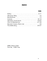
Страница 3: ...Page Safety 4 11 Warranty Policy 12 Specifications 13 Controls 14 18 Operation Instructions 19 26 Care Maintenance 27 38 Standard Service Parts List 39 Troubleshooting 40 41 8000 Series Gas Part No 13...

Страница 4: ...IF IMPROPERLY OPERATED CAN CAUSE SERIOUS INJURY OR DEATH The most common causes of injury to the operator or bystander read and understand this manual to prevent injuries BLADE CONTACT TIP OVER RUN O...

Страница 5: ...s injury WARNING highlighted in orange indicates a potentially hazardous situation which if not avoided could result in death or serious injury CAUTION highlighted in yellow indicates a potentially ha...

Страница 6: ...d up and thrown by the blade Be sure the area is clear of other people before mowing Stop mower if anyone enters the area NEVER carry passengers Do not mow in reverse unless absolutely necessary Alway...

Страница 7: ...ar safety goggles or safety glasses with side shields when operating mower Data indicates that operators age 60 years and above are involved in a large percentage of riding mower related injuries Thes...

Страница 8: ...her attachments These can change the stability of the mower Keep all movement on the slopes slow and gradual Do not make sudden changes in speed or direction Avoid starting or stopping on a slope If t...

Страница 9: ...children out of the mowing area and under the watchful care of another responsible adult Be alert and turn mower off if a child enters the area Before and during backing look BEHIND and DOWN for small...

Страница 10: ...t fire and explosion caused by static electricity Never fill containers inside a vehicle or on a truck or trailer bed with a plastic liner Always place containers on the ground away from your vehicle...

Страница 11: ...ing Never make adjustments or repairs with the engine running unless otherwise specified Grass catcher components are subject to wear damage and deterioration which could expose moving parts or allow...

Страница 12: ...hose supplied by Dixon Industries Inc VOIDS ALL WARRANTY 6 The following items are not covered by this warranty policy a Pick up and delivery charges for transportation of mower to and from an authori...

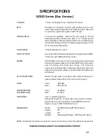
Страница 13: ...Overhead Valve Air Cooled Gasoline HorizontalShaft AluminumHead and Crankcase with Cast Iron Liners Full Pressure Lubrication Full Flow Filter Pulse type Fuel Pump Fixed Jet Carburetor ElectronicIgni...

Страница 14: ...s toward you TURNING Turning is controlled by moving one control lever slightly forward or rearward of the other To turn left move left lever rearward of the right lever To turn right move right lever...

Страница 15: ...s set parking brake before dismounting Release the parking brake before moving mower Note Engage parking brake before starting engine MOWER DECK LIFT The mower lift lever is extra long has an assist s...

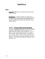
Страница 16: ...y close off the damper Closing off the damper causes it to become stiff making it difficult to fully extend the damper in order to open the adjustment THE PRODUCT IS NOT DAMAGED To restore adjustment...

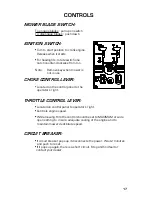
Страница 17: ...LEVER Located on the control panel to the operator s right THROTTLE CONTROL LEVER Located on control panel to operator s right Controls engine speed While mowing throttle control should be set to MAX...

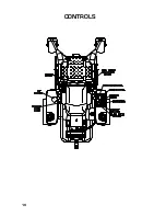
Страница 18: ...18 CONTROLS...

Страница 19: ...ower without complete knowledge of all controls and their functions During initial operation learning to drive set throttle at slow speed BEFORE OPERATING MOWER 1 Read and observe all safety instructi...

Страница 20: ...interlocks for your safety 1 The engine will not start if the mower blades are engaged 2 The engine will not start unless the steering control levers are neutral OUT position 3 The engine will stop if...

Страница 21: ...ENGINE SHOULD NOT START 3 In a SAFE AREA away from bystanders start the engine place throttle setting at maximum or full Engage the blade drive through the electric clutch switch Raise slightly off o...

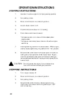
Страница 22: ...rt position When engine starts release ignition key Key will return to run position 8 Move throttle control lever to the wide open or maximum setting for actual operation of the mower deck Engine must...

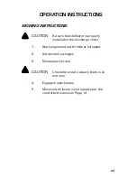
Страница 23: ...perly installed on the discharge chute 1 Start engine and set throttle at full speed 2 Set desired cut height 3 Release park brake CAUTION Check the area to assure there is no one near 4 Engage mower...

Страница 24: ...rp blades throughout the cutting season As a rule of thumb never cut off more than 1 3 of the total grass blade length Correct mowing height can reduce weeds and disease by 50 to 80 The following gras...

Страница 25: ...own bracket and replace the pin and rotating pin clip to lock them in place Release the seat latch and rotate the counterbalanced seat support frame upward and forward To return the seat to the operat...

Страница 26: ...achine To unlock the transmission lift the seat see Page 25 rotate the transmission hex valve located on the top of each transmission approximately one turn counter clockwise To re engage the transmis...

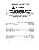
Страница 27: ...common safety practices with tools ve all common safety practices with tools ve all common safety practices with tools ve all common safety practices with tools ve all common safety practices with to...

Страница 28: ...N BATTERY STORAGE DO NOT remove battery from mower Clean top of battery and terminals with baking soda and water Identify each cable so they can be reconnected to the correct terminal Disconnect cable...

Страница 29: ...nal 25 degree bevel 4 Check balance of blade by positioning the blade on a nail or blade balance pedestal Grind the blade on the end that is heavier until both sides balance 5 Install blade flat washe...

Страница 30: ...TENANCE LUBRICATION 1 Engine Follow engine manufacturer s recommendation 2 Deck spindles Lubricate with 3 shots only every 100 hours 3 Mower chassis Lubricate with 3 shots only every 50 hours see zerk...

Страница 31: ...should be approximately 1 3 8 below top of oil tank Replenish as needed with SAE 20W 50 motor oil DO NOT OVERFILL When checking the oil level be very careful to keep the reservoir clean Change the oi...

Страница 32: ...and counter clockwise to decrease brake holding power As the brake holding power is increased the force required on the handle to engage the brake increases 3 Set the brake for the holding power requi...

Страница 33: ...the 1 2 nut on the U shaped holding bracket and swivel the headlight vertically to adjust the height of the beam Tighten the bracket nut 3 Replace headlight in fuel tank 4 Swivel the headlight horizo...

Страница 34: ...T REPLACEMENT PROCEDURE To remove hydrostat pump drive belt The hydrostat pump drive is equipped with a spring loaded belt take up 1 Raise seat See instructions on Page 25 2 Remove hold down bolts fro...

Страница 35: ...check to see that the drive wheels are not turning 7 Repeat steps 3 6 for the other side 8 Shut off engine before removing the blocks 9 Return the seat to the operating position To adjust neutral spri...

Страница 36: ...ering control mechanism 2 Move the levers inboard to the operating position 3 Loosen the set screw of the clamp collars which lock the upper arms to the lower arms 4 Raise or lower the arms for desire...

Страница 37: ...Stop the machine and shut off the engine 3 Adjust the forward stop of the control levers on the side which appears to be faster to limit the forward travel of the control levers until the mower tracks...

Страница 38: ...e mower deck in the number 3 deck height position 5 Loosen the jam nuts on the front and rear deck hangers 6 Rotate the 2 outer spindles so the blades point outboard 7 Adjust front hangers to level de...

Страница 39: ...TER PART NUMBERS Refer to engine manufacturer s manual for recommen dations regarding frequency of service required for engine oil changes and air filter maintenance Protect your engine investment use...

Страница 40: ...eck fuel filter open fuel valve Faulty fuel pump consult dealer Spark plug wire loose or grounded check spark plug wires Spark plugs faulty or improperly gapped check spark plug Electronic ignition de...

Страница 41: ...Drive belt broken or slipping replace drive belt Pump arm loose or disconnected tighten or reconnect Hydraulic oil system low add oil By pass valves in free wheel position tighten by pass valves Hydro...

Страница 42: ...42 NOTES...

Страница 43: ...____ ___________________ ___________________ ___________________ ___________________ ___________________ ___________________ ___________________ ___________________ ___________________ _______________...

Страница 44: ...STRIES INC a BLOUNT International Inc Co P O Box 1569 Coffeyville Ks 67337 0945 620 251 2000 8000 Series Gas Model 8025 Part No 13637 xxxx W W W W WARNING ARNING ARNING ARNING ARNING The engine exhaus...

Отзывы: