background image

23

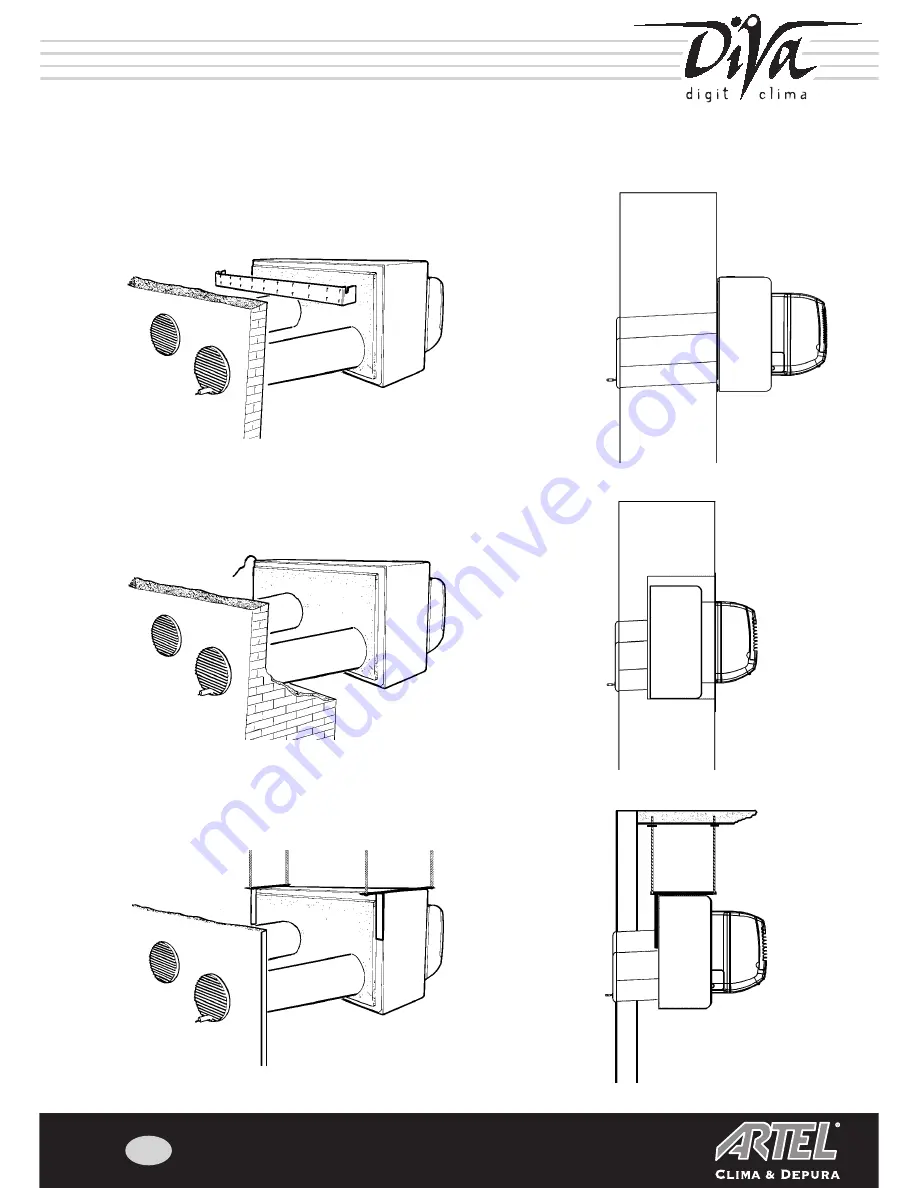
We provide an installation diagram below that summarises all the information found in the respective chapters that explain the
various types of installation possible:

Wall installation (Page. 4)

Built-in installation (Page 7)

Ceiling installation (Page 12)

Содержание RDW 9RN

Страница 1: ...E CUSTOMER The position of the air conditioner is extremely important for both correct operation and the comfort of the room or area Choose the unit s position together with the customer while taking into consideration the following points A The air must be distributed as evenly as possible throughout the room taking into consideration that warm air tends to rise and cool air tends to fall B The f...

Страница 2: ...he flow of air from the rear grills must not be sent into a closed room because if this expulsed air is injected into an area without free circulation the temperature will rise and the unit will begin malfunctioning with lower yield H The unit s controls must be easily accessible to facilitate routine maintenance operations I The condensate produced during operation must be eliminated without crea...

Страница 3: ...tion diagram below that summarises all the information found in the respective chapters that explain the various types of installation possible Wall installation Page 4 Built in installation Page 7 Ceiling installation Page 12 ...

Страница 4: ...wall into the holes drilled for air suction and expulsion making sure that the pipe lined with condensate proof material can be fitted into hole A as shown in Figure 1 N B The air inlet and outlet pipes supplied have a maximum length of 40 cm for this reason if the depth of the wall is less these pipes must be cut For installations with pipes longer than 40 cm please contact your nearest Technical...

Страница 5: ...t must be inserted inside the condensate drainage in order to prevent water from freezing inside the pipe in low temperature installations Cut the length of pipe as required depending on how far it must protrude outside bearing in mind that it must protrude from the air hosing sealing grill by 1 cm IMPORTANT make sure that the downward inclination of the condensate drainage outwards is in the rang...

Страница 6: ... con densate drainage pipe to exit correctly see Figure 9 Rear grills At the end of installation the grills must be applied to the air circulation pipes As above this particular measure will ensure better unit operation because not only will the air be filtered and therefore the heat exchange system will remain cleaner and maintain yield over a longer period of time but also will prevent the depos...

Страница 7: ...ith condensate proof material can be fitted into hole A as shown in Figure 1 N B The air inlet and outlet pipes supplied have a maximum length of 40 cm for this reason if the depth of the wall is less these pipes must be cut For installations with pipes longer than 40 cm please contact your nearest Technical Assistance Center or your Manufacturer s technical commercial contact person 5 Make sure t...

Страница 8: ...ondensate drainage in order to prevent water from freezing inside the pipe in low temperature installations Cut the length of pipe as required depending on how far it must protrude outside bearing in mind that it must protrude from the air hosing sealing grill by 1 cm IMPORTANT make sure that the downward inclination of the condensate drainage outwards is in the range of from 0 to 5 fig 8 open the...

Страница 9: ... provided the power supply cable might keep the unit raised from the wall Insert the unit into the recess made in the wall and pass the condensate drainage hose along the air expulsion pipe and check the stability of the air conditioner Push the unit in towards the wall behind it this operation can be made easier by inserting the rectan gular ABS plate supplied at the base of the opening Rear gril...

Страница 10: ...ly will the air be filtered and therefore the heat exchange system will remain cleaner and maintain yield over a longer period of time but will also prevent the deposit of leaves or other clogging material in the pipes and infiltration by birds or other small animals These grills can be quickly removed and cleaned whenever necessary AIR SUCTION VIEW OF AIR CONDITIONER REAR GRILLS AIR EXPULSION CON...

Страница 11: ...HE CONDENSATE DRAINAGE AND VENTILATION HOLES THE OUTLINE REGARDS THE UNIT S REAL PERIMETER AND NOT THE OPE NING TO BE MADE IN THE WALL WHICH MUST CONSEQUENTLY BE INCREASED BY 10 MM ON EACH SIDE AND 20 MM IN HEIGHT IMPORTANT THESE DIMENSIONS ARE IN MILLIMETERS 31 ...

Страница 12: ... from rear Facing the inside of the unit Facing the inside of the unit Left bracket seen from rear fig 2 fig 1 SSEMBLY PROCEDURE Whenever auxiliary condensate drainage must be performed read the paragraphs provided on Page 18 immediately a Remove the screws indicated in Figure 1 from both the right and left parts of the air conditio ner see drawing and put them carefully aside in order to avoid co...

Страница 13: ... glass because the air expulsion pipes must reach the outdoors Apply the two brackets as described in Figures 3 and 4 with threaded holes for the application of the M8 eyelets for the fastening of the chains Insert all the extra long screws supplied with the ceiling installation to fasten the brackets as shown in Figure 4 Remember not to use the screws previously removed from the unit for the fast...

Страница 14: ...all is less these pipes must be cut For installations with pipes longer than 40 cm please contact your nearest Technical Assistance Center or your Manufacturer s technical commercial contact person 4 Make sure that the air expulsion pipe hole A in Figure 5 is lined with condensate proof insulation material along its entire length Whenever the pipes supplied are not used remember to internally line...

Страница 15: ...ents drilling to a depth of more than 1 5 cm this installation is not fixed because minimum oscillations might shift the air suction and expulsion pipes 4 Apply plastic pipes of diameter and length adequate to the distance of the air conditioner from the glass itself to the flanges applied on the rear panel making sure that the pipe lined with condensate proof material is inserted in hole A in Fig...

Страница 16: ...condensate drainage in order to prevent water from freezing inside the pipe in low temperature installations Cut the length of pipe as required depending on how far it must protrude outside bearing in mind that it must protrude from the air hosing sealing grill by 1 cm IMPORTANT make sure that the downward inclination of the condensate drainage outwards is in the range of from 0 to 5 fig 11 open t...

Страница 17: ...ill looking at the unit from the rear in order to permit the con densate drainage pipe to exit correctly see Figure 3a Rear grills At the end of installation the grills must be applied to the air circulation pipes As above this particular measure will ensure better unit operation because not only will the air be filtered and therefore the heat exchange system will remain cleaner and maintain yield...

Страница 18: ...oth the vibration of the structure and the crushing of the condensate drainage pipe CONNECT TO THIS RUBBER PIPE AN EXTENSION PIPE THAT PERMITS THE EXCESS CONDENSATE CREA TED BY THE UNIT TOWARDS A SPECIAL DRAIN OR INTO A TEMPORARY COLLECTION TRAY THAT MUST BE REGULARLY CHECKED AND DRAINED IMPORTANT incorrect installation can cause water leakage along the wall Whenever the installation of auxiliary ...

Страница 19: ...rthing system IMPORTANT The air conditioner comes with overheating protection for the external battery that triggers whenever the fan breaks or the heat exchanger clogs When the protection triggers the unit must be accurately cleaned by opening the upper panel and sucking any impurities present In case of malfunction of the fan repair or replace as required The air conditioner comes with its own p...

Страница 20: ...40 Cod 000495 NOTE ...

Отзывы: