DITEC Entrematic PID24 Скачать руководство пользователя страница 3

3

IP2114 • 2011-09-20

DECLARATION BY THE MANUFACTURER

Manufacturer: DITEC S.p.A. 
   

via Mons. Banfi, 3 


21042 Caronno Pertusella (VA) - ITALY.

Herewith  declares  that  the  microwave  non-contact  push 

button PID24 is in conformity with the provisions of the fol-

lowing EC directives: 
-  R&TTE Directive 1999/5/EC
-  EMC Directive 2004/108/EC 

Caronno Pertusella, 20-09-2011 

Marco Zini       


                     (Managing Director)

GENERAL SAFETY PRECAUTIONS

This installation manual is intended for professionally com

-

petent personnel only.
Read the instructions carefully before beginning to install 
the product. Incorrect installation may be a source of dan-
ger.

Packaging materials (plastic, polystyrene, etc.) must not be 

allowed to litter the environment and must be kept out of 
the reach of children for whom they may be a source of 
danger.
Before beginning the installation check that the product is 
in perfect condition.
For repairs or replacements of product only original spare 

parts  must  be  used.  These  instruction  must  be  kept  and 

forwarded to all possible future user of the system.

To  handle  electronic  parts,  wear  earthed  antistatic 

conductive bracelets.

1.  TECHNICAL DATA

Power supply    

24 V AC/DC

Stand-by absorption 

50 mA

Operating absorption 

80 mA

Frequency 

24,150 GHz

Output contact


30 V / 1 A max (resistive load) 

Protection degree 

IP43

Temperature 

da -20° C a +55°C

2. REFERENCE

[1]  Cover

[2]  Sensor support frame
[3]  Detection module

[4]  Command terminal board
[5]  Detection area range adjustment trimmer
[6]  Container
[7]  LED / Operating indicator
[8]  Detection mode selection switch

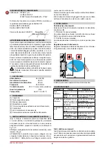
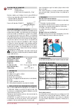
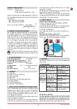
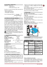
3.  INSTALLATION AND ELECTRICAL CONNECTIONS

(Fig. 1) Fix the container [6] securely to a flat surface or place 
a round recessed box (not supplied) in a position suitable 
for the designated use and placed as shown in fig. 1 and 3.
Make the connections to the command terminal board [4], 

as shown in Fig. 4. 

WARNING: The product must be connected to an extra-low 
voltage power source (SELV = Safety Extra Low Voltage) 
which is protected from overcurrent and shortcircuiting.


Fasten the sensor support frame [2] to the container using 
the supplied screws.

NB: Avoid placing items that may move in the detection area 
i.e. curtains, signs or plants.  

4.   ADJUSTMENTS

Selecting type of detection.

Select the type of detection using the selection switch [8].
T / TOGGLE: Toggle function.
A first detection closes the contact which remains closed 

until a second detection takes place.

P / PULSE: Pulse function.
A detection activates the contact for a short period of time 
(approx. 1 s).

Detection area adjustment

Adjust  the  detection  area  range  by  using  the  adjustment 
trimmer [5], as shown in the figure.

100

500

-

+

-

+

5.  INDICATIONS

The LED [7] comes on when the output relay is activated.

6. TROUBLESHOOTING

Problem

Cause

Solution

It does not 

work

Power supply vol-

tage

Check the power supply

Faulty connection

Check the wiring and 

the connector

It does not 

always work

Sudden change in 

the detection area 

conditions

Check the installation 

conditions

Check the detection 

area range.

It works by 

itself

There is an object in 

the detection area

Remove the object

The sensor is subject 

to vibrations

Install the sensor firmly

The  sensor  detects 

the moving door 

wing

Adjust the detection 

area correctly

All right reserved

All data and specifications have been drawn up and checked 
with the greatest care. The manufacturer cannot however 
take any responsibility for eventual errors, ommisions or in

-

complete data due to technical or illustrative purposes.

EN

Содержание Entrematic PID24

Страница 1: ...4 rev 2011 09 20 Manuale di installazione sensore microonde a sfioramento Microwave non contact pushbutton installation manual Notice d installation capteur hyperfréquence no pas contact Bedienungsanleitung für Berührungslosen Schalter Manual de instalación del sensor de microondas por rozamiento Manual de instalação do sensor de microondas de proximidade IT EN FR DE ES PT DITEC S p A Via Mons Ban...

Страница 2: ...ernativa predisporre una scatola ad incasso tonda non di nostra fornitura in una posizione adeguata all utilizzo preposto e orientato come indicato in fig 1 e 3 Effettuare i collegamenti alla morsettiera comandi 4 come indicato in fig 4 ATTENZIONE il prodotto deve essere collegato ad una sorgente di alimentazione in bassissima tensione di sicu rezza SELV Safety Extra Low Voltage protetta contro so...

Страница 3: ...t surface or place a round recessed box not supplied in a position suitable for the designated use and placed as shown in fig 1 and 3 Make the connections to the command terminal board 4 as shown in Fig 4 WARNING The product must be connected to an extra low voltage power source SELV Safety Extra Low Voltage which is protected from overcurrent and shortcircuiting Fasten the sensor support frame 2 ...

Страница 4: ...tive disposer une boîte à encastrer ronde hors fourniture sur un emplacement adapté à l utilisation orientée comme indiqué sur la fig 1 et 3 Réaliser les raccordements au bornier des commandes 4 comme indiqué sur la fig 4 ATTENTION le produit doit être raccordé à une source d alimentation en très basse tension de sécurité TBTS protégée contre les surintensités et les courts circuits Fixer le châss...

Страница 5: ...en und wie in Abb 1 und 3 angegeben ausrichten DieAnschlüsse an das Klemmbrett der Steuerungen 4 wie in Abb 4 angegeben herstellen ACHTUNG Das Produkt muss an eine gegen Überstrom und Kurzstrom geschützte Stromversorgungsquelle mit Sicherheitsspannung SELV Safety Extra Low Voltage angeschlossen werden Den Rahmen der Sensorhalterung 2 am Gehäuse mit den beigepackten Schrauben festschrauben ANM Kein...

Страница 6: ...o trar redonda no suministrada por nosotros en una posición adecuada para el uso dispuesto y orientado como se indica en la fig 1 y 3 Efectúe las conexiones en el terminal de bornes 4 como se indica en la fig 4 ATENCIÓN El producto debe conectarse a una fuente de alimentación de tensión extra baja de seguridad SELV Safety Extra Low Voltage protegida contra sobrecorrientes y cortocircuito Fije el m...

Страница 7: ... modo estável ou em alternativa predispor uma caixa redonda de encaixe não fornecido pelo fabricante numa posição adequada para o uso previsto e orientado conforme indicado na fig 1 e 3 Realizar as ligações à bateria de bornes dos comandos 4 conforme indicado na fig 4 ATENÇÃO o produto deve ser ligado a uma fonte de ali mentação com uma tensão de segurança muito baixa SELV Safety Extra Low Voltage...

Страница 8: ... MASSY Tel 33 1 64532860 Fax 33 1 64532861 www ditecfrance com DITEC GOLD PORTA ERMESINDE PORTUGAL Tel 351 22 9773520 Fax 351 22 9773528 38 www goldporta com DITEC SVIZZERA BALERNA Tel 41 848 558855 Fax 41 91 6466127 www ditecswiss ch DITEC ENTREMATIC NORDIC LANDSKRONA SWEDEN Tel 46 418 514 50 Fax 46 418 511 63 www ditecentrematicnordic com DITEC TURCHIA ISTANBUL Tel 90 21 28757850 Fax 90 21 28757...

Отзывы: