64
Network Guide
Maintain consistent polarity when connecting controllers and devices to the transformer. That
is, the 24V COM terminal of each controller and each peripheral
may
be connected to the
same terminal on the secondary side of the transformer. This transformer terminal must be
connected to the building's ground.
Recommended 24V Power Cable
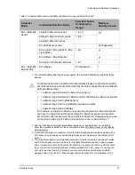
The table below lists Distech Controls' recommended power cable.
24V Power Supply Connection
Use an external fuse on the 24VAC side (secondary side) of the transformer or DC power sup-
ply, as shown in
and
, to protect all controllers against power line spikes.
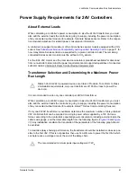
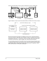
For any given number of devices, wire the power supply as shown in
Maintain consistent polarity when connecting controllers and devices to the transformer. That
is, the 24V COM terminal of each controller and each peripheral should be connected to the
same terminal on the secondary side of the transformer.
Figure 38: Power wiring – 24VAC: Maintain Consistent Polarity with all Controllers’ Power Connections
Table 14: Distech Controls Recommended 24V Power Cable
Cable Type
AWG - Number
of Conductors
Non-Plenum Applications (FT4)
Plenum Applications (FT6)
Part Number
O.D. (Ø)
Part Number
O.D. (Ø)
18-2
CB-W181P-1002
5.0mm 0.20in.
CB-W181P-2051 5.0mm 0.20in.
16-2
CB-W161P-1031
4.8mm / 0.19in.
CB-W161P-2062
4.8mm / 0.19in.
14-2
CB-W141P-1081
7.2mm / 0.29in.
CB-W141P-2013
7.2mm / 0.29in.
Connecting the power source to Electrical System Ground is not a requirement for
proper system operation. However it is good installation practice to do so in order to
maintain the same potential between all controllers and Protective Earth.
Controller 2
Transformer
Controller 1
AC
24V AC/DC
24V COM
Fuse: 4 A Max .
Fast Acting
24 VAC
OPTIONAL : Connect to Electrical System
Ground - At Power Supply Only
24V AC/DC
24V COM
Содержание ECB-VAV
Страница 1: ...User Guide Network Guide...
Страница 6: ...Table of Contents 4 Network Guide...
Страница 52: ...50 Network Guide...
Страница 70: ...68 Network Guide...
Страница 110: ...108 Network Guide...
Страница 121: ...LonWorks Troubleshooting Network Guide 119...
Страница 122: ...120 Network Guide...
Страница 124: ...122 Network Guide...
Страница 128: ...126 Network Guide...
Страница 134: ...132 Network Guide Figure 75 Example of How to Set a DIP Switch to 82 ON B A For example 82 A 1010 B 010...
Страница 136: ...134 Network Guide...
Страница 137: ...Network Guide...
Страница 138: ...Network Guide_UG_24_EN...


