


14(35)
User manual in Original
Dok. ref: User manual 500A-ATF-K Rev. F
DISPERATOR AB
Tel: +46 8 724 0160
E-mail: [email protected]
Mälarvägen 9, SE-141 71 Segeltorp, Sweden Fax: +46 8 724 6070
Web page: www.disperator.se
6.
Installation Instructions
6.1.
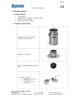
Assembly of Disposer
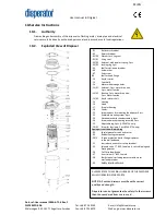
6.1.1.
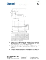
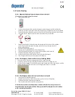
Mounting of the Disposer with a ATF-K Assembly
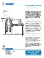
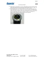
Dismount the ATF-assembly by loosening the three clamping screws and prying off the locking ring
carefully so that the thread is not damaged. The drain opening must be 90 mm (3,543 in.) in diameter
with an embossing. Place the AT-nipple including a gasket through the drain opening. From under the
sink, slip the gasket and the upper clamping ring up and over the AT-nipple. Next, while holding these
two parts in place, attach the lower clamping ring to the AT-nipple. Push the gasket and the two
clamping rings further up the AT-nipple. Slide the locking ring onto the AT-nipple until it falls into place
in the groove just above the 3" BSP, Male thread of the AT-nipple. Tighten the three clamping screws
until the entire ATF-assembly is seated evenly and tightly against the sink. Screw on the BS-flange to
the AT-nipple, make sure that it is sealed. Mount the disposer onto the BS-flange.
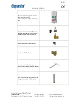
If a 3” ball valve has been ordered as an optional accessory between the sink and disposer, an extra
nipple 3” BSP, Male will be included in delivery. The nipple is needed to connect the lower outlet of
the ball valve to the BS-flange and disposer.
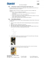
6.1.2.
Mounting and Support against Floor/Floor plate
Mounting of models 510A and 515A, delivered without legs as standard
The weight of disposer models 510A and 515A allows them, in most cases, to be hung vertically under
the mounting assembly (e.g. under a sink). The standard delivery of these models will therefore not
include legs. However, if they are to be placed standing on the floor / floor plate (e.g. beside a peeling
machine / dishwasher) these models must be fitted with legs. If legs have been ordered it is specified
on the delivery note.
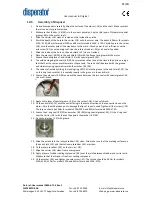
To minimize the risk of injuries, two persons shall always be present when the disposer is installed.
Below describes three different approaches, depending on the availability of tools at the installation
site.
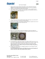
Place the disposer tightly against the flange of the mounting assembly, by using one of below
mentioned hoist methods; make sure that the rubber seal is correctly placed. Tighten the six screws
with nuts evenly; the rubber seal should be compressed approximately 1mm.
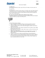
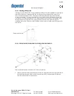
Hoist alternative 1
Trolley, see picture below.