background image

Danish Interpretation Systems 


User Manual 


User Manual DDS 5900 


41

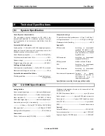
Technical Specifications 

9.1 

System Specification  

Overall


system


characteristics


The  microphone  system  conforms  to  IEC  60914,  the 
international  standard  for  conference  systems.  However 
the  functionality  of  an  interpreter  unit  differs  from  the 
standard. 

System


Audio Performance


Sound quality  .....24 bit audio @ 32 kHz sampling frequency 

Measured from the audio input of a conference unit to the 
headphone output of a conference unit: 

Audio frequency response ......................65 Hz ‐ 16 kHz (‐3 dB) 

Total harmonic distortion at 1 kHz ....................................< 0.1% 

Dynamic range ...........................................................................> 80 dB 

Weighted signal‐to‐noise ratio  ....................................> 85 dB(A) 

Cabling


and


System


Limits


Cable type (min. specification)  .......Cat5e, AWG 24, screened 

Maximum cable length in one chain  ................................... 150 m 

System


Environmental


Conditions


Working condition  .......................................... Fixed, stationary or 

 transportable 


Temperature


range


To guarantee specified performance...... 5 Deg C. to 40 Deg C. 

Storage temperature .................................. ‐20 Deg C. to 60 Deg C 

Maximum relative humidity ...................................................< 80% 

Approvals


EMC emission  

According  to  harmonized 
standard  EN  55103‐1  and 
FCC rules part 15, complying 
with  the  limits  for  a  class  A 
digital devices 

EMC immunity  

According  to  harmonized 
standard EN 55103‐2 

pprovals  

EMC a

Affixed with the CE mark 

ESD  

According  to  harmonized 

10

standard EN 55 3‐2 

Mains harmonics  

According  to  harmonized 

3‐1 

standard EN 5510

Environmental requirements   Contains 

no 

banned 

substances  as  specified  in 
UAT‐0480/100 

(e.g. 

no 

cadmium or asbestos) 

Specifications


are


subject


to


change


without


notice


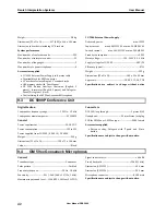
9.2 

CU 5905 Specifications  

Analog


Section


Audio output signal type ........................electronically balanced  

Nominal output level ..............................0 dBm at nominal input 

Max. output level............................................ 4.9V RMS 

 +16 dBm 

Audio input signal type ...........................electronically balanced  

Nominal input level (In 1 is switchable).........................................  

....................... 0 dBm or ‐10 dBm (0.775V RMS or 0.245V RMS) 

Max. input level  ............................................. +15 dBm (4.5V RMS) 

Analog Audio in impedance ......................................50‐100 kohm 

Connectors


Chain – Conference units (DCS‐LAN) .................................2xRJ45 

Maximum  total  number  of  units  to  be  connected  to  both 
outputs on a CU 5905: 

DC 5980P Conference Units .................................  up to 60 pieces  

Audio output............................... 4 pieces XLR3 male connectors  

Audio input.................................2 pieces XLR3 female connector 

LAN (TCP/IP) ....................................................................1 piece RJ45 

EEM.................................................................. 1 contact closure input 

General


Default IP address ......................................................... 192.168.10.1 

Power consumption............................................... max. 150W/48V 

Supply voltage for DC 5980 units ............................... 125W/48V 

Содержание DDS 5900

Страница 1: ...DDS 5900 User Manual Danish Interpretation Systems DIS Digital Discussion System DDS 5900 Digital Discussion System ...

Страница 2: ...retation Systems User Manual Copyright 2012 DIS User Manual DDS 5900 02 05 2012 No part of this publication may be reproduced or utilised in any form or by any means without permission in writing from the publisher ...

Страница 3: ...icrophone 9 5 5 Using the Interactive Menu 23 5 5 1 Overview 23 5 5 2 Navigate through the menu 23 3 2 System technology 9 3 2 1 Sound transmission 10 3 2 2 Features 10 3 2 3 Cabling 10 5 6 Web Browser Setup and Control 24 5 6 1 CU 5905 Setup browser 24 5 6 2 CU 5905 Mic Control browser 31 3 3 System components 10 3 3 1 DDS 5900 Conference System 10 3 3 2 Supported units DCS 6000 System 10 5 6 3 U...

Страница 4: ...tion Protocol45 10 1 General Protocol behaviour 45 k 10 1 1 TCP IP soc et connection 45 10 1 2 Command structure from External l to Contro CU 5905 46 10 1 3 Command structure from CU 5905 to al Extern Control 46 10 1 4 Seat numbering 47 10 1 5 CU 5905 reply to commands 47 10 1 6 Retrieving system status 47 10 2 Microphone Control 47 10 2 1 Commands from External Control to CU 5905 47 10 2 2 Comman...

Страница 5: ...ked or covered This apparatus should not be placed in a built in installation unless proper ventilation is provided or the manufacturer s instructions have been adhered to 9 Do not install near any heat sources such as radiators heat registers stoves air ducts or other apparatus including amplifiers that produce heat 10 Do not install the unit in a place exposed to direct sunlight excessive dust o...

Страница 6: ...ted in the vicinity of overhead power lines or other electric light or power circuits or where it can fall into such power lines or circuits When installing an outdoor system extreme care should be taken to keep from touching such power lines or circuits as contact with them might be fatal 23 Object and Liquid Entry Never push objects of any kind into this apparatus through openings as they may to...

Страница 7: ...ipment is operated in residential commercial or light industrial environments The equipment generates uses and can radiate radio frequency energy and if not installed and used in accordance with the user manual it may cause harmful interference to radio communications You are cautioned that any changes or modifications not expressly approved in this manual could void quipment your authority to ope...

Страница 8: ...2 5 Warranty The units are minimum covered by 24 months warranty against defects in materials or work anship m User Manual DDS 5900 8 ...

Страница 9: ...isten to it through headphones DDS 5900 Digital Discussion System comprises of one Central Unit and a number of Conference Units and Gooseneck Microphones 3 1 1 CU 5905 Central Unit Figure 3 1 A CU 5905 Central Unit The central unit is the core of the DDS 5900 Digital Discussion System Only one CU 5905 can be used in each system 3 1 2 DC 5980P Portable Conf Unit Figure 3 1 B DC 5 80P Confer nce ni...

Страница 10: ...using a PC or a control system such as AMX or Crestron 3 2 3 abli g C n The DDS 5900 system is using screened CAT5e cabling F UTP or U FTP ensuring a very cost effective installation and easy set up of portable systems The conference units are daisy chain connected to the central unit The number of units which can be connected to a central unit depends on length of the feeding cable nd the length ...

Страница 11: ...light green After about 15 seconds the display in the CU will be visible and the Led s in the button overlay on the DC 5980P will flash until the units are registered less than 60 seconds 7 Check that the units are working by touching the Speak button Please refer to section 6 DC 5980P Conference Unit for details 8 Change the unit type according to the attached overlay Please refer to section 6 2 ...

Страница 12: ...ng the CU 5905 web browser 4 3 Cabling guidelines The DC 5980P Conference Units are connected to the CU 5905 Central Unit using Cat5e F UTP or U FTP screened cables however the following guidelines has to be observed Maximum cable length in one chain is 150 m before inserting RP 6004 Repeater in a chain This includes interconnection cables between the units The maximum usable cable length depends ...

Страница 13: ...an be connected to both Chain outputs simultaneously on a CU 5905 Central Unit in total using only the supplied CU 5900 Power Supply If only one Chain is used the information in the table above must be used Length of Feeding Cable Length of inter connecting cable Total cable length Max number of DC 5980P Using both output 10 m 1 m 2x39 m 2x30 30 m 1 m 2x58 m 2x29 50 m 1 m 2x76 m 2x27 100 m 1 m 2x1...

Страница 14: ...h JB 6104 Total cable length Number of JB 6104 Max number of DC 5980 P 10 m 3 m 2x46 m 2x13 2x26 30 m 3 m 2x63 m 2x12 2x24 50 m 3 m 2x83 m 2x12 2x24 100 m 3 m 2x127 m 2x10 2x20 Figure 4 4 D Number of units connected using JB 6104 Junction Box using two chains on CU 5905 User Manual DDS 5900 14 ...

Страница 15: ...upply will automatically be powered up The indication in the switch is lighting Green when power is switched On A red light indicates that power is connected to the central unit but the unit is not switched On Standby Figure 5 1 B Back view of CU 5905 1 Power Supply input Connection of the external CU 5900 Power Supply 48V 3A The power supply is provided together with the CU 5905 Figure 5 1 C CU 5...

Страница 16: ...n Message EEM audio signal 5 2 Audio Schematic Figure 5 2 A DDS 5900 Digital Discussion System Audio Schematic 5 3 Installation The CU 5905 Central Units can be placed on a table or d c installed in a standar 19 ra k When installing in a 19 rack the supplied 19 brackets shall be fixed to the front side of the CU 5905 Central Unit by unscrewing the crews holding the top and button cover and then fi...

Страница 17: ...80P Units The DC 5980P Conference Units are connected to the CU 5905 using EC 6001 xx Cat5e cables This is the basic connection of the system Both of the DCS LAN connectors on the CU 5905 can be used for connecting DC 5980P Conference units Please refer to section 4 4 1 CU 5905 DC 5980P one chain for information about the number of units which can be connected using one chain Refer to section 4 4 ...

Страница 18: ...figuring the system and controlling the conference units from the PC Please refer to section 5 6 Web rowser B for more information Hint On older PC s it might be needed to setup a fixed IP address on both the PC and the CU Note Depending on the type of PC a Crossed LAN cable has to be used Instead of using a Crossed LAN cable a LAN Router can be inserted Figure 5 4 B Connecting the DDS 5900 Digita...

Страница 19: ... controlling nd the conference units from the PC a or iPad Please refer to section 5 6 Web Browser for more information Figure 5 4 C Connecting the DDS 5900 Digital Discussion System to a PC and an iPad 5 4 4 Connecting an audio recorder The CU 5905 is connected to the DC 5980P EC 6001 xx Ca Conference Units using t5e cables This configuration is used when Floor sound or sound from one or more mic...

Страница 20: ...e external mixer where the control or equalisation is done The sound from the audio mixer is then send back to he CU using the Audio In 1 input t Use the Group selection for the four outputs and make seat selection for each group Refer to section 5 6 Web Browser item 8 Important If Out A is send to the mixer the following settings must to be done CU 5905 Setup Audio Loudspeaker Control Microphone ...

Страница 21: ...U 5905 can be sed for connecting DC 5980P Conference units u In this example two units are configured as Interpreter Units and DH 6021 Headphone is connected to the units Sound from the Interpreter Units can then be heard in the headphones connected to the Chairman and Delegate Units Figure 5 4 F Connecting the DDS 5900 Digital Discussion System with interpretation functionality User Manual DDS 59...

Страница 22: ...21 Headphone is connected to the units Sound from the Interpreter Units can then be heard in the headphones connected m e to the Chair an and D legate Units A wireless language distribution system like DCS 6000 Digital Infrared Language System can then be connected to the Audio Out connectors B C and D where the source to the outputs are configured as the Floor and interpreter channels Refer to se...

Страница 23: ...ew of the menu structure however for a general description of the settings in the menu refer to the section 5 6 Web Browser where all CU 5905 settings are explained Figure 5 5 A Menu overview 5 5 2 Navigate through the menu Navigation in the menu and changing parameters is done by activation the 5 button keypad Cycle through the menu items Blue marking with the four arrow buttons Left Right Up Dow...

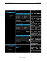
Страница 24: ...t The CU 5905 Web Browser Control has been tested with the following browsers IE8 9 Firefox 10 Safari and Chrome Other browsers might work but have not been tested Version of IE prior to v8 will not work Figure 5 6 A CU 5905 Setup The next tables show all menu items in the browser menu and a detailed description of the settings available Menu Settings Description 1 There are six menu options in th...

Страница 25: ...me can be used to connect to the CU 5905 with a browser instead of using the IP address After a hostname is assigned type the following in the browser http hostname local where hostname is to be replaced with the assigned name IP con guration fi Select Dynamic if the CU is connected to a network with DHCP server Otherwise select Static and assign a fixed IP address to the CU Default IP addr 1 ess ...

Страница 26: ...le in the loudspeakers 6 Input Output Control The Audio In 1 Volume is used to set the level of the input signal The gain of the Audio In signal can be set to 0 dB or 10 dB When set to 10 dB the input signal is amplified 10 dB The Audio In 1 signal can be routed to the Loudspeakers including headphones in the conference units as well as to Out A output using the two selection buttons The Audio In ...

Страница 27: ... Ch 2 is selected for an output Out A B C or D the corresponding group is disabled in the Group Setup Grou Setup p The conference units can be assigned individually to four groups Group A is always used as the source to the built in loudspeakers A unit can be selected in Group A and or in one of the other three groups If a unit is not selected in Group A the audio from this unit will not be availa...

Страница 28: ...s button is disabled The Seat Number is a numerical in the range 1 to 65535 When the mouse curser is moved to a seat number field the red light ring in the microphone in the corresponding conference unit is flashing until the curser is moved to another field or Submit Changes has been activated This feature makes it easy to re number the units If units are disconnected they are marked with a yello...

Страница 29: ...h irman units ga a The number of Max speakers Delegates defines the maximum number of Delegate conference units which are allowed to speak at the same time Please observe that a Chairman Unit can always be switched ON as long as the number set in Max Speakers Total are not exceeded Maximum requests defines how many delegates requesting to speak which can be inserted into the Request list 12 Operat...

Страница 30: ... until the microphone turns off The default value is 4 sec Auto Off When Microphone Auto Off is set to On a conference unit will automatic turn off the microphone when the delegate stops talking The time is determined by the Auto Off time setting The Automatic Off Time sets the time from the delegate stops speaking until the microphone turns off The value can be set from 5 to 60 seconds in 5 secon...

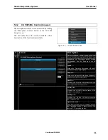
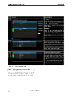
Страница 31: ...tching On Off microphone and depending on Operation mode setting microphones into the Request to speak queue Speak Brings the Delegate Microphone Speak list See 17 later in this table Request Brings the Delegate Microphone Request list See 18 later in this table Next On Pressing the Next On button turns on the first request on the request list All Del Off Pressing the All Del Off button turns off ...

Страница 32: ...ith delegates and chairmen Clicking a name will turn on the m crophone i If a unit is disconnected the seat will be greyed out and cannot be activated 18 Delegate Microphones Requests Shows the list of seats with delegates and chairmen Clicking a delegate name will place the delegate in the request queue A Chairman will not be placed in the request queue If a unit is disconnected the seat will be ...

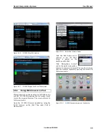
Страница 33: ...t in full screen mode Open the CU 5905 Browser application using the Safari browser on the iPad Then select Add to Home screen Figure 5 6 G Select Add to Ho Screen me Click the Add button and a shortcut to the CU 5905 Setup is placed on the op deskt on the iPad Click Microphone Control and in the similar way make a shortcut for this screen as well The two shortcuts can now be activated separately ...

Страница 34: ...maximum requests is reached The green Request lamp in the delegate unit in top of the queue will flash slowly indicating that this unit is the next to be switched On The green Request lamp in the other delegate unit in the queue will light up steadily When one of the units speaking is switched Off the first delegate unit in the queue is automati cally switched On This mode will normally be used wi...

Страница 35: ...XLR socket Turn the hex key counter clockwise to lock the gooseneck microphone to the unit and turn the hex key clockwise to unlock the gooseneck microphone o fr m the unit 4 Loudspeaker Built in loudspeaker The loudspeaker is turned Off when the microphone in the unit is active The built in loudspeaker is always Off when the unit is configured as Interpreter Unit 5 DCS LAN connection Two RJ45 soc...

Страница 36: ...h overlays are available Please refer to the section 9 6 Accessories 6 2 4 Configuration of the unit The unit is default configured as Delegate with Speak and Mute button Any unit can be re configured either as a chairman delegate without Mute button or interpreter unit To change unit type press the volume buttons and simultaneously and keep depressed for 3 seconds until the Speak light starts fla...

Страница 37: ...tion Ch 1 selection is indicated with light in Led 1 and Ch 2 selection is indicated with light in Led 2 With no light the Floor channel is selected 6 5 Interpreter Unit When the unit is configured as Interpreter unit the buttons has the following functionality 1 Headphone volume control The button decreases the sound level in the connected headphone and the button increases the sound level The so...

Страница 38: ...up when sound from the unit is send to the central unit he microphone is inserted in the XLR socket in the icrophone and can be locked to the unit with a 1 5 mm hex allen key The lock is accessible from the small hole close to the XLR socket Turn the hex key counter clockwise to lock the gooseneck microphone to the unit Turn the hex key clockwise to unlock the gooseneck microphone from the unit T ...

Страница 39: ... the units t c nce units Check he channel sele tion on the confere Check the plug from the headphone is firmly inserted in the headphone socket Check that the light ring on the microphone on the interpreter unit is lighting and that he gooseneck microphone is firmly inserted in the microphone ocket s There is no sound in the built in loudspeakers Check the Loudspeaker Volume setting using either t...

Страница 40: ...e browser Check that the CU 5905 is connected to the same network as the PC Check the LAN cables The CU 5905 browser application will not open in iPad Check the IP address using the interactive menu on the CU LAN setup IP address setup IP address Use this IP address in the browser Check that the iPad is connected to the correct wireless access point Check that the CU 5905 is connected to the same ...

Страница 41: ...103 1 and FCC rules part 15 complying with the limits for a class A digital devices EMC immunity According to harmonized standard EN 55103 2 pprovals EMC a Affixed with the CE mark ESD According to harmonized 10 standard EN 55 3 2 Mains harmonics According to harmonized 3 1 standard EN 5510 Environmental requirements Contains no banned substances as specified in UAT 0480 100 e g no cadmium or asbe...

Страница 42: ...al 87 Weight 935 g Dimensions W x H x D 180 x 52 x 99 mm Approvals CE KC CCC UL TÜV Specifications are subject to change without notice 9 3 DC 5980P Conference Unit Digital Section Loudspeaker frequency range 150 Hz 15 kHz Loudspeaker maximum power 2 1W RMS General Power requirement 24 48 V DC to 3W Power consumption 1W Power supplied from CU 5905 EX 6010 PS 6000 Weight 500 g Dimensions W x H x D ...

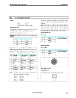
Страница 43: ...HT 4 0V BLU BLU 5 0V BLU WHT BLU WHT 6 48V GRN GRN 7 Outgoing BRN WHT BRN WHT 8 Outgoing BRN BRN Note If other color codes are used then the four pairs ar onnected e c as follows Pair 2 Pin 1 2 Pair 3 Pin 3 6 Pair 1 Pin 4 5 Pair 4 Pin 7 8 The phase of the pairs must be correct and the wiring spec as stated in Cat5e EIA 568 B have to be followed Note Cat6 and Cat7 cables can normally only be termin...

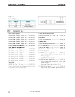
Страница 44: ...6001 50 Connection Cable 50 m 10 03 24502 Cable Clamp AC 5900 Cable Clamp 100 pieces 15 12 61101 The clamp will prevent the cable getting stuck between the table and the bottom of the unit if the unit is moved Transportation and Storage Box SB 5980 Storage Box for 10 DC 5980P GM 15 12 61001 Headphones DH 6021 Stereo headphones 14 11 03055 Expansion units JB 6104 Junction Box with 4 outputs 15 09 0...

Страница 45: ... Control Application Protocol Customer applications can include but are not limited to AMX or Crestron room control systems PC or micro controller based applications e g for button mimics and camera control applications 10 1 General Protocol behaviour 10 1 1 TCP IP socket connection A TCP IP socket connection to the CU 5905 must be established for the external control application protocol to becom...

Страница 46: ...SP data CR command SP data LF SP Space 0x20 32 CR Carriage return 0x0D 13 LF Line Feed 0x0A 10 line terminations Notice also there is a space between the command and data If a command does not carry any data space is possible but not required The CU is not sensitive to upper lower case Example mic_on 212 CR Turn on microphone a seat 212 Command mic_on data 212 The mic_on command carries a seat num...

Страница 47: ... microphone is already turned on The microphone is no longer connected to the system Speak list is already full max_speakers and delegate interrupt is not on 10 1 6 Retrieving system status The CU supports streaming of status When an external control application issues a mic_status or audio_status command the CU responds by sending the microphone system status The same goes for audio status Hereby...

Страница 48: ...from request list f the CU removes the unit from the request list it replies with a mic_request_off command I Clear request list mic_all_requests_off CR Clear the request list The CU responds by issuing a mic_request_off command for each microphone that is removed from the request ist l Set next microphone on mic_next_on CR d turns rophone from the request list Turns off first microphone in the sp...

Страница 49: ...st out manual Manual and vox Voice Active mode Can be set to auto A fifo First he CU responds by sending a mic_mode command T Set interrupt mode mic_interrupt mode CR t abil Se ity to interrupt Defines whether microphones should interrupt or not ones interrupt icrophones do not interrupt mode Can be on microph and off m he CU responds by sending a mic_interrupt command T Retrieve microphone status...

Страница 50: ... console 10 2 2 Commands from CU 5905 to External Control 10 2 2 1 10 2 2 2 10 2 2 3 10 2 2 4 10 2 2 5 Microphone on mic_on seat no CR microphone is turned on A Microphone off mic_off seat no CR microphone is turned off A Microphone in request list mic_request_on seat no request microphone is in position CR A serted into request list request position informs about the position in the request list ...

Страница 51: ...phones to interrupt mode on microphones interrupt and off microphones do not interrupt Seat Number seat_number seat number seat state seat name CR Seat information This information is sent from the CU to an external control application when the external control application quests micro re phone status mic_status seat num ger ranging from 1 to 65535 ber The seat number identification of a conferenc...

Страница 52: ...ve or passive Command error command_error error text CR The CU has received an unknown command error text is a text explaining the fault case Examples command_error unknown command CR command_error syntax error CR 10 3 Audio Control 10 3 1 Commands from External Control to CU 5905 10 3 1 1 10 3 1 2 Set loudspeaker volume loudspeaker_volume volume CR t the vo Se lume of loudspeakers for all confere...

Страница 53: ...udio path audio_path path on off CR his comm io s t T and defines aud connection in the sys em path Indicates which connection is being controlled Possible values mic_to_speaker mic_to_floor nein_1 li _to_speaker linein_1_to_lineout_A linein_1_to_floor ed from mic neinput_1 to speakers lineoutput floor on off Indicates whether the audio is being rout rophones li he CU responds to this command by r...

Страница 54: ...R Adjust the level of line output signal outp ut Indicates which output is being controlled Possible values A B C D level The level of line output ranges from 41 to 0 The value 41 indicates Off whereas values from 40 to 0 ndicates attenuation in dB i Define audio path audio_path path on off CR his comm o s t t T and defines audi connection in he sys em path Indicates which connection is being cont...

Отзывы: