7
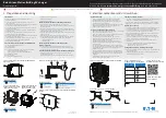
20mA~90mA
8.
Station ID
Off: Default
4.
Power Socket
5.
Power On/Off
6.
LAN Plug
–
SUML series
5. BASIC OPERATION
The section explains the Basic Daily Operation of using the Smart USB MultiChartger
for the electrical power charging
. It does not contain information on syncing or backup which is
specific the operating system of the smart devices.
5.1
Typical Pre-Conditions
a.
Proper power cord connecting from an active wall plug to Power Socket (4.2.4) at the back panel.
b.
Make sure the Power is switch on (4.2.4)
c.
Have the USB Connection Cable for your smart devices.
5.2
Connecting Sequence
a.
Connect USB Connection Cable to the smart devicel.
b.
Plug the USB end of the cable to any of the Charging and Data Sync port (4.1.A)
c.
The LED will show its charging mode for that port (4.1.B).
d.
The display will automatically switch the latest plugin port and display the port number (4.1.D)
e.
The current port’s
current is display in Amps (4.1.E).
f.
When the LED for the port stay lit on the specific port, then the charging is completed and the
smart device can be remove (4.1.B)
6.
NETWORK CONTROL
The Network Control comprises of proprietary network protocol and application software
to help you easily manage the charging devices either in the local network or through an
international base organization. Currently the application only supports Microsoft
Window’s platform.
Plugin a LAN Cat. cabling to 4.2.6 to start.
6.1 Software Installation
Take the file provided that came with the Smart MultiCharger w/ LAN software and
extract it if necessary so that it is in the executable exe form. Double click on the icon to
start the installation and allow for it in the User Account Control if applicable. Click next
to step through the language selection, licensing, and the file location for the program.