DirectCM DCM1100i Скачать руководство пользователя страница 16

Assembling / Dissmebling  


16

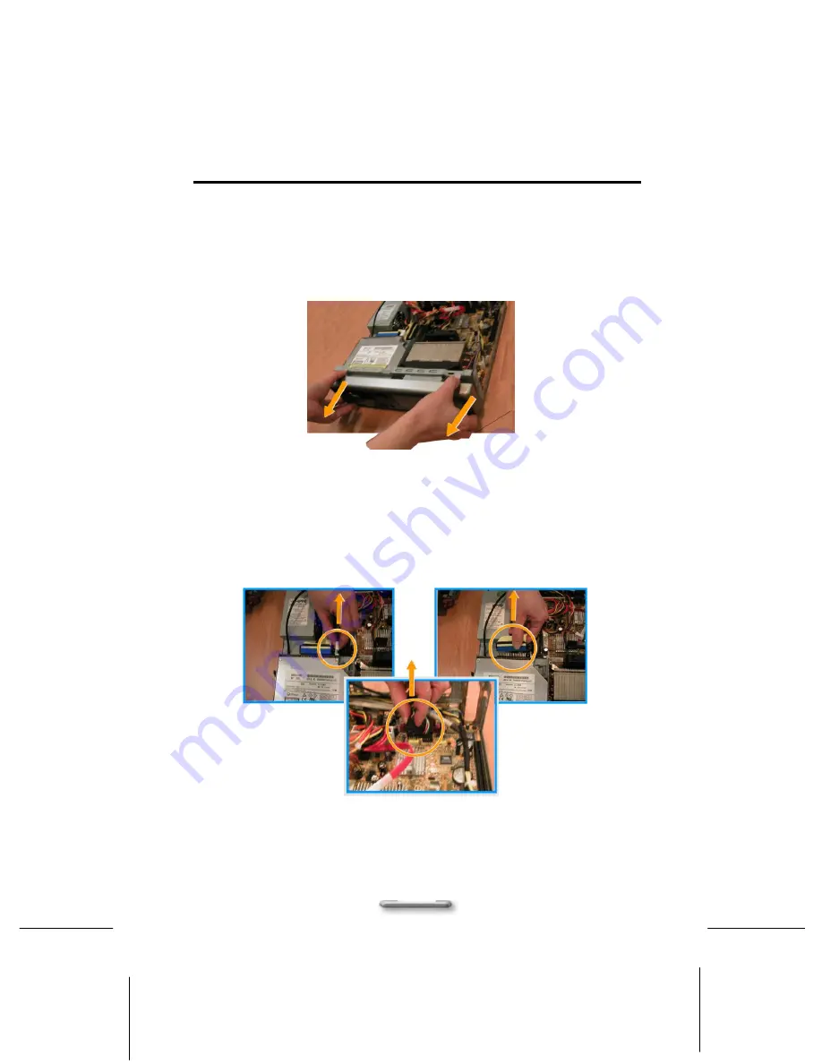
Removing of ODD & Card Reader Frame 

i. 

Remove the front cover with disengaging metal 
tab that hook on bottom and move it forward to 
open it. 


Figure 5.1 

ii. 

Before removing ODD & Card Reader frame 
from the main body, you must first disconnect 
the card reader connector, IDE connector and 
power connector, as shown in Figure 5.2 


Figure 5.2 

Card 
Reader 
Connecto

IDE 
Connector


Power 
Connector 

Содержание DCM1100i

Страница 1: ...1 D DC CM M1 11 10 00 0i i User Manual...

Страница 2: ...f fo or r d de es sk kt to op ps s With the carefully place vent location DCM1100i is can be place vertically or horizontally on office desktops allowing you some much needed flexibility In addition...

Страница 3: ...ury and the risk of damage please read this manual and follow al safety guidelines General Information Read all instructions included in this manual Save all instructions for future use Adhere to all...

Страница 4: ...l products plugged in the wall outlet should not exceed the fuse rating Do not push objects through cabinet slots as they could touch dangerous voltage points or damage internal parts This could resul...

Страница 5: ...of the FCC Rules These limits are designed to provide reasonable protection against harmful interference in a residential installation This equipment generates uses and can radiate radio frequency ene...

Страница 6: ...Chapter3 14 Assembling Disassembling Error Bookmark not defined Removing the Case Cover 14 Removing of Hard Disk Rack 15 Removing of ODD Card Reader Frame 16 Removing the VGA Card 17 Removing the Powe...

Страница 7: ...e adequate ventilation internal components can overheat and be damaged as a result Do not damage or destroy the computer box while unpacking Rather save the box in case you need to ship the system in...

Страница 8: ...CM1100i System on and off When you power on this LED embedded in Power switch will light blue If the button is held down for one second the unit will enter Suspend mode and if held down for four secon...

Страница 9: ...EE1394 Connector 1394 devices can be connected via these ports 7 Air Inlet This inlet allows air inside or outside chassis to be inhaled and exhaled for better air flow 8 ODD device Insert DVD ROM int...

Страница 10: ...ayers to this jack for recording on your computer or playback through the Line Out device Line Out jack green Connect audio devices such as headphones or speakers to this jack Microphone jack pink Plu...

Страница 11: ...ity mechanism when you place the switch in lock position the chassis cover cannot be opened 2 Kensington Lock A hardware security mechanism which locks the chassis to prevent hardware from being stole...

Страница 12: ...the peripheral device of IEEE1394 and USB please connect the USB and IEEE1394 connectors as shown in shown in Figure 2 4 Figure 2 4 1 USB Connector Connect to USB connector for any USB device 2 IEEE1...

Страница 13: ...Assembling Dissmebling 13 About Card Reader connector For using card reader please connect the USB card reader connector as shown in shown in Figure 2 5 Figure 2 5...

Страница 14: ...em mb bl li in ng g Removing the Case Cover i Lay the unit flat face the rear panel of the unit ii Switch the Chassis Lock to unlock cover position as shown in Figure 3 1 Figure 3 1 iii Pull the cove...

Страница 15: ...the whole hard disk rack from the main body please disconnect the flat cable and power cord of the hard disk as shown in Figure 4 1 and Figure 4 2 ii S w i tch the Chassis Lock to HDD unlock position...

Страница 16: ...metal tab that hook on bottom and move it forward to open it Figure 5 1 ii Before removing ODD Card Reader frame from the main body you must first disconnect the card reader connector IDE connector an...

Страница 17: ...te as indicated by below drawing circle and pull forward you may totally opened the ODD card reader rack as shown in Figure 5 3 Figure 5 3 Removing the VGA Card i Lift up the VGA board shield plate fr...

Страница 18: ...ted in step1 and slightly move the VGA board to right side as indicted in step 2 to unhook the board from staple Figure 6 2 Perform the above steps in reverse order to install the VGA card Removing th...

Страница 19: ...ame as shown in Figure 7 2 Figure 7 2 Installing Uninstalling the Hard Disk Drive i Hook your hands inward onto the plastic holder as indicated in below drawing step 1 and then lift it upward from the...

Страница 20: ...he hard disk rack in position by simply placing it back to main frame as shown in Figure 8 3 Figure 8 3 Installing Removing the CPU i Remove the CPU heat sink before removing the CPU To remove the CPU...

Страница 21: ...heat sink from motherboard as shown in Figure 9 2 Figure 9 2 iii Orient the CPU with the socket place the CPU on socket it should slide into place without the use of force as shown in Figure 9 3 Rear...

Страница 22: ...ever and click it into its latch at the side of the socket as shown in Figure 9 4 above to lock the CPU in position Figure 9 4 v Place the heat sink back to motherboard and screw each side of the heat...

Страница 23: ...t stand is intended for the DCM1100i to stand securely in the upright position Please assemble it on the chassis as shown in Figure 10 1 and Figure 10 2 Figure 10 1 Figure 10 2 The DCM1100i System wit...

Страница 24: ...Assembling Dissmebling 24 Figure 10 3...

Страница 25: ...1 AC x 1 Expansion cards Rear Low profile PCIe16x slots x 1 Technical Specifications Chassis Ultra Small Desktop Dimensions 3 4 H x 11 5 W x 12 6 D 3 Drive Bays Bay 1 5 25 external slimline Bay 2 3 5...

Страница 26: ...h priority IT challenges Those experts determined the top three issues to be 1 Better asset management 2 Reduced downtime 3 Minimized desktop visits With this information in hand they developed Intel...

Страница 27: ...Assembling Dissmebling 27 All contents in the specifications are subjected to change without notice...

Отзывы: