background image

5

English

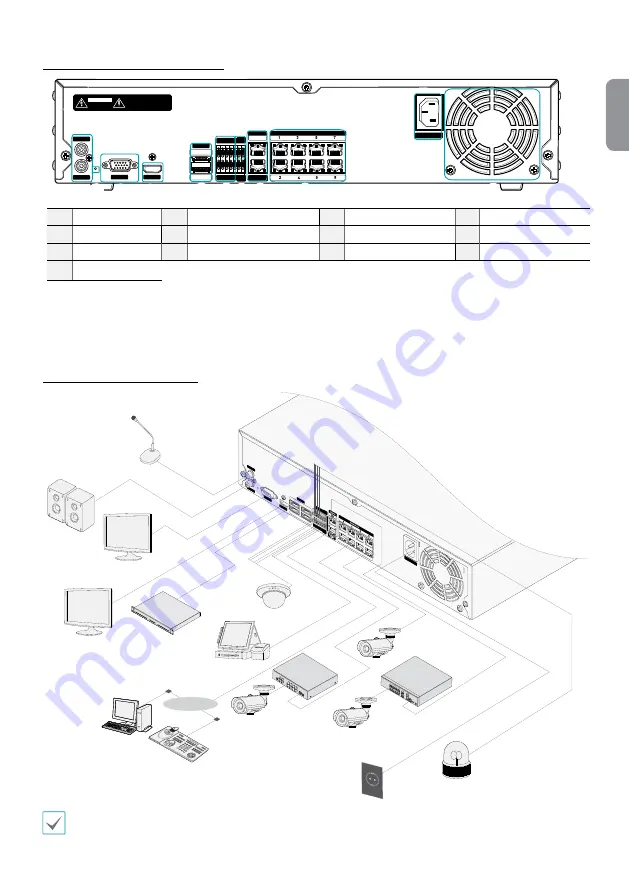
<DR-4100P Series, DR-4200P Series> 

AUDIO IN

AUDIO OUT

VGA OUT

HDMI

eSATA

NETWORK

CLIENT

VIDEO IN / PoE

NC     C     NO   AR I   G 

RS -485

-          +

A/1   A/2    A/3   A/4      G   Tx        Rx

RS    -232

CAUTION : TO REDUCE THE RISK OF ELECTRIC SHOCK.

DO NOT REMOVE COVER (OR BACK).

NO USER-SERVICEABLE PARTS INSIDE.

REFER SERVICING TO QUALIFIED

SERVICE PERSONNEL.

CAUTION

RISK OF ELECTRIC SHOCK

DO NOT OPEN

VIDEO IN

Ext.

100-240V~

1

2

12

4

5

7

!

68 9

0

3

@

#

1

Audio Ports

2

Factory Reset Button

3

VGA Out Port

4

HDMI Out Port

5

eSATA Ports

6

Alarm Connection Ports

7

RS485 Port

8

RS232 Port

9

Network Port

0

Video In / Ext. Port

!

Video In / PoE Ports

@

Power In Port

#

Vent

Connections on the Rear Panel 

AUDIO OUT

NC     C     N

O   AR I   G

  RS -485

-          +

A/1   A/2

    A/3   A/4

      G   Tx

        Rx

RS    -23

2

AUDIO IN

VGA OUT

HD OUT

eSA

TA

1

3

2

4

B

D

F

H

100-240V~

Direc

tIP™ S

witch

Video Enc

oder

Microphone

Speaker

VGA Monitor

HDMI Monitor

eSATA Storage Device

Sensor

DirectIP™ Gigabit 

PoE Switch

Keyboard

Power

Alarm

POS

IDIS Center 

Remote 

Monitoring

Network 

Camera

Network 

Camera

Analog 

Camera

Video Encoder

Network

 This connection diagram is for the DR-6100P and DR-6200P Series.

Содержание Idis DR-4100P Series

Страница 1: ...DR 6100P Series DR 4100P Series DR 6200P Series DR 4200P Series Network Video Recorder Quick Guide Powered by...

Страница 2: ...aged B If liquid is spilled or objects have fallen into the equipment C If the equipment has been exposed to rain or water D If the equipment does not operate normally by following the operating instr...

Страница 3: ...Product Applicable in the European Union and other European countries with separate collection systems Thismarkingshownontheproductoritsliterature indicatesthatitshouldnotbedisposedwithotherhouseholdw...

Страница 4: ...0 USB Ports For more details on front panel buttons refer to the manual This document covers the 8 16 and 32 channel network video recorders The NVRs are identical except for the number of cameras an...

Страница 5: ...Port 5 eSATA Ports 6 Alarm Connection Ports 7 RS485 Port 8 RS232 Port 9 Network Port 0 Video In Ext Port Video In PoE Ports Power In Port Vent Connections on the Rear Panel AU DIO OU T NC C NO AR I G...

Страница 6: ...n remote control buttons refer to the manual Getting Started Setup Wizard Setup Wizard only appears during initial booting When you login as an administrator account after initial booting you can use...

Страница 7: ...on Use this button to scan for and register cameras Pressing the Scan button displays the following submenu Rescan Scan for DirectIP cameras that were not scanned automatically Go To Camera Moves the...

Страница 8: ...er the necessary camera login info This option is inactive for DirectIP cameras because they do not require logins Video Display Area Left click on the video display area to toggle between split scree...

Страница 9: ...e Setup button while in Live mode to bring up the Live menu on the top of the screen Press Setup once more to hide the menu Use the Arrow buttons on the front panel of the NVR or the remote control to...

Страница 10: ...nd will NOT work with other browsers IDIS Web does not work in Microsoft Windows 8 metro UI Setup IDIS Web 1 Launch Internet Explorer and then enter the following information in the address bar http I...

Страница 11: ...Setup folder in the CD and run setup exe On Microsoft Windows Vista or User Account Control window may pop up Click Allow and follow the instructions in the installation window to proceed with the ins...

Страница 12: ...er ID is admin without a password You can change User ID and Password in the User menu Device Registration To use the functions provided by IDIS Center you must first register a device and add the dev...

Страница 13: ...ce group will be displayed on the right To modify a device group that has been registered select a device group and click E on the bottom of the Sites panel Modify Device Group window will appear You...

Страница 14: ...tact your FEN server administrator Address Monitoring Port Search Port Audio Port Enter the device name used to register the device to FEN If FEN feature is not enabled on the device deselect FEN chec...

Страница 15: ...oothly in a remote program I O Alarm In 4 TTL NC NO programmable 2 4V NC or 0 3V NO threshold 5VDC Alarm Out 1 relay output NC NO 2A 125VAC 1A 30VDC Alarm Reset In 1 TTL terminal block Internal Buzzer...

Страница 16: ...IDIS Co Ltd For more information please visit at www idisglobal com...

Отзывы: