Dionex LC20 Скачать руководство пользователя страница 1

LC20 CHROMATOGRAPHY ENCLOSURE

OPERATOR’S MANUAL

© 1993 Dionex Corporation

Document No. 034859

Revision 02

September 1993

Содержание LC20

Страница 1: ...LC20 CHROMATOGRAPHY ENCLOSURE OPERATOR S MANUAL 1993 Dionex Corporation Document No 034859 Revision 02 September 1993 ...

Страница 2: ...PUBLICATION IS PROVIDED AS IS WITHOUT WARRANTY OF ANY KIND DIONEX CORPORATION DOES NOT WARRANT GUARANTEE OR MAKE ANY EXPRESS OR IMPLIED REPRESENTATIONS REGARDING THE USE OR THE RESULTS OF THE USE OF THIS PUBLICATION IN TERMS OF CORRECTNESS ACCURACY RELIABILITY CURRENTNESS OR OTHERWISE FURTHER DIONEX CORPORATION RESERVES THE RIGHT TO REVISE THIS PUBLICATION AND TO MAKE CHANGES FROM TIME TO TIME IN ...

Страница 3: ... 3 2 3 Interior Layout 2 4 2 3 1 Component Panel 2 5 2 3 2 Rheodyne Injection Valve 2 6 2 3 3 Self Regenerating Suppressor 2 7 2 3 4 Leak Sensor 2 7 2 3 5 Separator Columns 2 7 2 3 6 Guard Columns 2 7 2 3 7 Column Select Valve 2 8 2 3 8 Detector Cells 2 11 2 3 9 DS3 Detection Stabilizer Optional 2 11 2 4 Rear Panel 2 12 2 4 1 Cell Cables 2 13 2 4 2 Waste Line 2 13 Doc 034859 02 9 93 i ...

Страница 4: ... 3 Inoperative Column Select Valve 4 5 4 4 Column Select Valve Air Leaks 4 5 4 5 Peak Ghosting 4 6 4 6 Non Reproducible Peak Height or Retention Time 4 6 4 7 Abnormal Retention Time or Selectivity 4 6 5 Service 5 1 Introduction 5 3 5 2 Tube Fitting Installation 5 3 5 3 Restriction in the Hydraulic System 5 4 5 4 Injection or Column Select Valve Liquid Leaks 5 4 5 5 Column Select Valve Air Leaks 5 ...

Страница 5: ... 3 A 3 Hydraulics A 3 A 4 Insulation A 4 B Installation B 1 Facilities Required B 3 B 2 Installation Instructions B 4 B 2 1 Stacking Modules B 4 B 2 2 Waste Lines B 5 B 2 3 Leak Control B 6 B 2 4 Liquid Line Connections B 6 B 2 5 Detector Cells B 9 B 2 6 Column Installation B 12 B 2 7 SRS Installation Optional B 13 B 2 8 Solenoid Valve Connections to the Pump B 14 Contents Doc 034859 02 9 93 iii ...

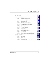
Страница 6: ...Contents iv Doc 034859 02 9 93 ...

Страница 7: ...1 Introduction 1 1 Overview 1 3 1 2 About This Manual 1 3 1 3 Product Safety Information 1 4 Doc 034859 02 9 93 1 1 ...

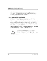
Страница 8: ...LC20 Chromatography Enclosure 1 2 Doc 034859 02 9 93 ...

Страница 9: ...30 stainless steel automated injection valve P N 044171 1 2 About This Manual This manual describes the operation maintenance and use of the L20 Chromatography Enclosure Chapter 1 Introduction introduces the product and conventions used in the manual and provides safety information Chapter 2 Description is a description of the physical aspects of the LC20 Chromatography Enclosure followed by a fun...

Страница 10: ...t for Measurement Control and Laboratory Use Section of this manual are flagged with key words and symbols to denote the nature of potential hazards These safety directives apply to all operators and service personnel The following safety reference symbols are marked in the instrument and this manual where necessary to alert the operator Indicates a potential hazard to the operator or damage to th...

Страница 11: ... Injection Valve 2 6 2 3 3 Self Regenerating Suppressor 2 7 2 3 4 Leak Sensor 2 7 2 3 5 Separator Columns 2 7 2 3 6 Guard Columns 2 7 2 3 7 Column Select Valve 2 8 2 3 8 Detector Cells 2 11 2 3 9 DS3 Detection Stabilizer Optional 2 11 2 4 Rear Panel 2 12 2 4 1 Cell Cables 2 13 2 4 2 Waste Line 2 13 2 4 3 Solenoid Interface 2 13 Doc 034859 02 9 93 2 1 ...

Страница 12: ...LC20 Chromatography Enclosure 2 2 Doc 034859 02 9 93 ...

Страница 13: ...s enough tubing in the LC20 Ship Kit P N 046300 to plumb two systems The LC20 does not require power Internal components are operated by the GP40 IP20 pump 2 2 Front Panel The front panel of the enclosure is the door It contains access to one or two Rheodyne injection valves 2 2 1 Rheodyne Injection Valve The Rheodyne injection valve is mounted on the component panel in a manner that allows its co...

Страница 14: ... slide out panel for mounting components Figure 2 1 illustrates the LC20 chassis See Section B 2 1 for recommended stacking configurations See Figure 2 2 for an illustration of the slide out component panel Figure 2 1 LC20 Interior Chassis LC20 Chromatography Enclosure 2 4 Doc 034859 02 9 93 ...

Страница 15: ...ide out panel The panel on the right side is standard in all LC20 enclosures When a dual channel module is ordered an opposite panel is factory installed on the left side see Figure 2 2 Figure 2 2 Component Panel Layout 2 Description Doc 034859 02 9 93 2 5 ...

Страница 16: ... the panel align it with the top and bottom tracks and push inward until it engages the second detent Press the second slide release and push the panel to its closed and locked position Various component arrangements are made possible by multiple mounting holes and slots The configuration shown here is only one of many offered by the enclosure 2 3 2 Rheodyne Injection Valve The Rheodyne injection ...

Страница 17: ... spills in the bottom of the enclosure and generates a signal when a leak occurs The sensor is located at the lower front corner of the left wall in the bottom tray Its cable exits through the rear service chase and must be connected to the GP40 pump 2 3 5 Separator Columns The column mount near the front of the component panel can accommodate up to two separator columns The column mount supports ...

Страница 18: ...he optional 28 MKa 4000 psi column select valve directs the flow of eluent and sample from the Rheodyne injection valve to either column A or B The column select valve can alternatively be used to switch in and out a separator column The column select valve is actuated by a pair of solenoids mounted on the rear panel which will be included only when the column select valve is installed The solenoi...

Страница 19: ...termediate connection between the valve slider and all tube fittings These bolts must be tightened evenly to provide uniform sealing pressure against the valve slider and ensure leak free operation For valve maintenance information refer to the Installation and Maintenance of the Dionex High Pressure Valve Document No 032678 Figure 2 3 Column Select Valve 2 Description Doc 034859 02 9 93 2 9 ...

Страница 20: ...sition selecting column A slider down 1 4 and 2 3 5 8 and 6 7 Switch in ON position selecting column B slider up 1 2 and 3 4 5 6 and 7 8 The valve is tested to operate leak free at 28 MPa 4000 psi After testing the valve pressure bolts are loosened to reduce stress on critical parts during storage Before shipment the pressure bolts are tightened to provide leak free operation at pressures up to 17...

Страница 21: ...of the Dionex High Pressure Valve Document No 032678 for additional information 2 3 8 Detector Cells Detector cells for the CD20 Conductivity Detector or the ED40 Electrochemical Detector are mounted on the component panel Their cables exit through one of the service chases on the rear panel 2 3 9 DS3 Detection Stabilizer Optional The DS3 improves baseline stability by damping fluctuations in temp...

Страница 22: ...2 4 Rear Panel The rear panel provides installation space for air and valve connectors see Figure 2 5 Figure 2 5 LC20 Rear Panel LC20 Chromatography Enclosure 2 12 Doc 034859 02 9 93 ...

Страница 23: ...ough the service chase in the rear panel see Figure 2 5 The injection valve waste lines should exit through the lower side slots of the enclosure 2 4 3 Solenoid Interface The air actuated solenoid valves used to control the injection valve and the column select valves if installed are controlled directly by the pump The solenoids are installed as pairs one pair is shown in Figure 2 5 Refer to the ...

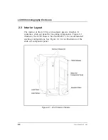
Страница 24: ...LC20 Chromatography Enclosure 2 14 Doc 034859 02 9 93 ...

Страница 25: ...3 Operation and Maintenance 3 1 Routine Operation 3 3 3 1 1 Sample Loading 3 4 3 2 Shutdown 3 7 3 3 Routine Maintenance 3 7 Doc 034859 02 9 93 3 1 ...

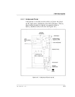
Страница 26: ...LC20 Chromatography Enclosure 3 2 Doc 034859 02 9 93 ...

Страница 27: ...sition eluent flows in from the pump and out to the column without entering the sample loop Sample flows from the syringe into the valve and through the sample loop and excess sample flows out to waste In the INJECT position eluent flows in from the pump through the sample loop and out to the column carrying the contents of the sample loop with it Figure 3 6 Injection Valve Schematic Doc 034859 02...

Страница 28: ...e valve Set the injection valve to its LOAD position Insert the syringe into the needle port on the injection valve see Figure 3 6 Overfill the sample loop with several sample loop volumes Excess sample will flow out through the waste line Leave the syringe in the needle port until the injection valve knob is turned to INJECT 2 Drawing sample through the waste line Place the injection valve into i...

Страница 29: ...Figure 3 7 Drawing Sample 3 Operation and Maintenance Doc 034859 02 9 93 3 5 ...

Страница 30: ...t 6 Place the valve in its LOAD position Insert the needle adaptor shipped with the Rheodyne valve into the needle port Push sample through the waste line Waste will exit the valve through the needle adaptor No sample to be analyzed will come into contact with the metal needle of the needle adaptor see Figure 3 8 4 Loading from an automated sampler See the autosampler operator s manual for instruc...

Страница 31: ...er to other modules The power actuator rod leading the power switch at the rear of the module will not operate if the door is open 3 3 Routine Maintenance Periodically check for leaks or spills inside the LC20 Locate and repair leaks and clean up spills Rinse all dried eluents especially when they include salt solutions or reagents off system components with deionized water or in the case of spill...

Страница 32: ...LC20 Chromatography Enclosure 3 8 Doc 034859 02 9 93 ...

Страница 33: ...ve System Backpressure 4 4 4 3 Inoperative Column Select Valve 4 5 4 4 Column Select Valve Air Leaks 4 5 4 5 Peak Ghosting 4 6 4 6 Non Reproducible Peak Height or Retention Time 4 6 4 7 Abnormal Retention Time or Selectivity 4 6 Doc 034859 02 9 93 4 1 ...

Страница 34: ...LC20 Chromatography Enclosure 4 2 Doc 034859 02 9 93 ...

Страница 35: ... Make sure all liquid line connections are tight 1 If the connections are made with Dionex ferrule fittings see Installation of Dionex Ferrule Fittings Document No 034213 for instructions 2 If the column select valve is plumbed into the system remove the valve from its mounting clip to improve access to all valve ports Use a wrench on the valve pressure bolt to prevent it from turning while tighte...

Страница 36: ...ten pressure bolts for optimum leak free operation Refer to Installation and Maintenance of the Dionex Inert High Pressure Valve Document No 032678 for torque requirements A column select valve port is scratched Replace the port face 4 2 Excessive System Backpressure Restriction in the hydraulic system 1 Check all liquid lines and valves for crimping or blockage Make sure ferrule fittings are not ...

Страница 37: ...kage Remove and replace any blocked tubing Reposition crimped or pinched tubes Air leak Air leaks are usually audible isolate and eliminate leaks Valve is incorrectly plumbed Check that the system is correctly plumbed Re plumb the system if necessary Pressure bolts on the column select valve are too tight Follow the procedure in Section 4 1 to loosen the pressure bolts if the column select valve i...

Страница 38: ...op with at least 10 loop volumes of deionized water or sample between sample injections 4 6 Non Reproducible Peak Height or Retention Time Column overloading 1 Change to a sample loop with a smaller volume 2 Dilute the sample Liquid leaks Locate and eliminate the leaks Also see Peak ghosting in Section 4 5 above 4 7 Abnormal Retention Time or Selectivity System is not equilibrated following an elu...

Страница 39: ...S grade deionized water Contaminated or degraded sample Take appropriate precautions when preparing and storing samples to prevent contamination and degradation Column is contaminated 1 Clean the column see Column Rejuvenation Procedures Technical Note 2R Document No 032036 2 If cleaning is unsuccessful replace the column 4 Troubleshooting Doc 034859 02 9 93 4 7 ...

Страница 40: ...LC20 Chromatography Enclosure 4 8 Doc 034859 02 9 93 ...

Страница 41: ...the Hydraulic System 5 4 5 4 Injection or Column Select Valve Liquid Leaks 5 4 5 5 Column Select Valve Air Leaks 5 5 5 6 Cleaning the Column Select Valve Slider 5 6 5 7 Replacing the Column Select Valve Port Face 5 9 5 8 Servicing the Rheodyne Injection Valve 5 9 Doc 034859 02 9 93 5 1 ...

Страница 42: ...LC20 Chromatography Enclosure 5 2 Doc 034859 02 9 93 ...

Страница 43: ...ide the part numbers and where applicable the revision number of the items you are ordering 5 2 Tube Fitting Installation The LC20 is plumbed with Dionex 10 32 ferrule fittings PEEK tubing is recommended for use throughout the system However ThermoFlare tubing may be installed where pressures are below 7 MPa 1000 psi this includes waste lines tubing from an autosampler to the Rheodyne valve inject...

Страница 44: ...sed by the column select valve disassemble the valve and clean the slider see Section Figure 2 4 Column Select Valve Slider Connections 5 4 Injection or Column Select Valve Liquid Leaks A poor seal between the ferrule sealing surface and the valve pressure bolt or between the port face and the valve slider may cause the column select valve to leak see Figure 2 3 The flow rate through the system ma...

Страница 45: ... Inert High Pressure Valve Document No 032678 for the torque requirements Use caution as overtightening may break off the bolt in the valve body 4 If tightening the pressure bolts does not stop the leak refer to Section 5 7 for instructions to replace the port face 5 5 Column Select Valve Air Leaks An air leak around the valve piston or cap results in excessive air consumption and may cause the va...

Страница 46: ...ringly Excess grease may contaminate the eluent 9 Press the piston back into the valve body 10 Make sure that the cap O ring is inside the cap Screw the cap back onto the valve body Tighten it only fingertight 11 Reconnect the air line to the valve 5 6 Cleaning the Column Select Valve Slider A dirty or plugged valve slider causes excessive system backpressure and may cause poor chromatographic per...

Страница 47: ...038709 11 Place the slider in a small container of deionized water or methanol Sonicate or agitate vigorously for several minutes 12 Rinse the slider with deionized water Blow any water out of the holes and inspect them for blockage Use a fine piece of wire 0 025 in to dislodge any remaining blockage Be careful not to scratch the slider surface If the blockage cannot be removed replace the slider ...

Страница 48: ...ts must be evenly tightened against the slider 128 in oz A special torque wrench kit P N 038943 is available from Dionex 17 Turn on the liquid flow and check for leaks Tighten the pressure bolts further if leaks appear Use caution as overtightening may break off the bolt in the valve body 18 If cleaning the valve slider does not eliminate the backpressure problem see the next section for instructi...

Страница 49: ... Turn on the liquid flow and check for leaks Tighten pressure bolts further if leaks appear For optimal leak free operation a torque wrench can be used to evenly tighten pressure bolts Refer to Installation and Maintenance of the Dionex Inert High Pressure Valve Document No 032678 for torque requirements Use caution as overtightening may break off the bolt in the valve body 7 Reconnect the tube fi...

Страница 50: ...LC20 Chromatography Enclosure 5 10 Doc 034859 02 9 93 ...

Страница 51: ...A Specifications A 1 Environmental A 3 A 2 Physical A 3 A 3 Hydraulics A 3 A 4 Insulation A 4 Doc 034859 02 9 93 A 1 ...

Страница 52: ...LC20 Chromatography Enclosure A 2 Doc 034859 02 9 93 ...

Страница 53: ...ons 50 cm high x 22 5 cm wide x 49 cm deep 20 8 in x 8 9 in x 20 4 in 6 cm clearance required in back of the module Weight 12 kg 25 lbs A 3 Hydraulics Rheodyne Injection Valve 35 MPa 5000 psi metal free or stainless steel rotary valve for low volume injections Column Select Valve 28 MPa 4000 psi metal free column select valve to direct eluent and sample to one of two columns The column select valv...

Страница 54: ...A 4 Insulation Dampening Dampens outside temperature variations by a factor of 5 to 10 over 10 minutes 2 to 4 over 60 minutes LC20 Chromatography Enclosure A 4 Doc 034859 02 9 93 ...

Страница 55: ...2 Waste Lines B 5 B 2 3 Leak Control B 6 B 2 4 Liquid Line Connections B 6 Injection Valve Connections B 7 B 2 5 Detector Cells B 9 External Cell B 9 Internal Cell B 10 B 2 6 Column Installation B 12 B 2 7 SRS Installation Optional B 13 B 2 8 Solenoid Valve Connections to the Pump B 14 Doc 034859 02 9 93 B 1 ...

Страница 56: ...LC20 Chromatography Enclosure B 2 Doc 034859 02 9 93 ...

Страница 57: ... environment that provides maximum consistency in ambient temperature and humidity In general you should avoid sun and proximity to hot equipment avoid heavy air drafts and sudden temperature changes not operate the enclosure in condensing atmospheres maintain specified ambient temperatures Connect gas air pressure to the solenoids on the rear panel see Figure 2 5 The gas air pressure is routed to...

Страница 58: ...to be stacked on top of each other up to a maximum height of four units The enclosure is three units high and should not be stacked on any other unit The enclosure should not have more than one single unit module on top of it such as a CD20 Conductivity Detector ED40 Electrochemical Detector or the EO1 Eluent Organizer P N 044125 Figure B 1 illustrates the recommended stacking configuration Lift t...

Страница 59: ...that it is not bent pinched or elevated at any point see Figure B 2 Minor leaks do not generally present a serious situation but they should be thoroughly rinsed with deionized water and dried to prevent salt solutions from crystallizing on the enclosure surfaces Neutralize acidic and caustic waste before disposal Dispose of wastes containing organic solvents in accordance with local regulations F...

Страница 60: ... IDs After selecting the appropriate tubing size see below you will need to cut the tubing to the lengths required to plumb the system However before cutting any tubing be sure that it is long enough to allow servicing the system e g you should be able to open the front door of the LC20 and slide the component panel out of the enclosure to its detent without putting stress on the tubing For 4 mm c...

Страница 61: ...stallation of Dionex Ferrule Fittings Document No 034213 provided in the LC20 Ship Kit Injection Valve Connections 1 Connect the eluent line from the pump pressure transducer to port 2 on the Rheodyne injection valve A label on top of the valve identifies ports 1 and 2 Ports 3 through 6 follow in sequence with port 6 close to port 1 on the opposite side from port 2 see Figure B 2 Connect a piece o...

Страница 62: ...e available contact the nearest Dionex Regional Office for information 5 Cut two pieces of tubing for waste lines Install a ferrule P N 043276 and fitting P N 043275 on one end of each of the pieces of tubing 6 Connect the ferrule fitting end of one of the waste lines to port 5 on the Rheodyne valve Connect the ferrule fitting end of the second waste line to port 6 Route the waste lines out throug...

Страница 63: ...tical detector connect the outlet of the separator column or suppressor to the detector cell inlet see Figure B 4 Route the tubing exiting the separator column or suppressor through one of the side slots on the LC20 Figure B 4 External Detector Cell Plumbing Schematic B Installation Doc 034859 02 9 93 B 9 ...

Страница 64: ...ough B 6 when installing a cell in the LC20 If the conductivity cell is installed inside the optional DS3 Detection Stabilizer see the DS3 Detection Stabilizer Operator s Manual Document No 034850 Figure B 5 Conductivity Cell Plumbing Schematic LC20 Chromatography Enclosure B 10 Doc 034859 02 9 93 ...

Страница 65: ...Figure B 6 Electrochemical Cell Plumbing Schematic B Installation Doc 034859 02 9 93 B 11 ...

Страница 66: ... 2 Reduce the flow rate to 2 0 mL min and verify that the pressure through the system with no columns installed is less than 690 KPa 100 psi 3 Install the separator column mounting clip by inserting it into one of the square holes at the front edge of the component panel see Figure B 7 If you are using the 4 mm suppressor columns orient the clip so the larger clips are toward the front If you are ...

Страница 67: ...et top of the separator column to the ELUENT INLET of the SRS Otherwise connect the separator outlet directly to the detector inlet 5 Snap the separator columns into the column clips on the component panel See Figure 2 2 for an illustration of the columns mounted in the clips The guard columns are held in place only by the connecting tubing B 2 7 SRS Installation Optional 1 For complete SRS techni...

Страница 68: ...ounting the bracket align the slots on the back of the SRS with the tabs on the mounting bracket Press in and then down to lock the SRS in place Lift up and pull out to remove the SRS if necessary B 2 8 Solenoid Valve Connections to the Pump Connect air actuated solenoid valves between pump and the LC20 for control of the column select and injection valves Refer to the pump operator s manual for i...

Страница 69: ... Detection Stabilizer 2 11 E Environmental specifications A 3 F Facilities required B 3 Front panel 2 3 G Guard columns 2 7 H Hydraulic specifications A 3 I Injection valve 2 3 2 6 Sample loading 3 4 Solenoid interface 2 13 B 14 Injection valve connections B 7 Installation B 3 Column installation B 12 Detector cell plumbing B 9 Facilities required B 3 Injection valve connections B 7 Leak Control B...

Страница 70: ...al description A 3 Front panel 2 3 Interior components 2 4 Rear Panel 2 12 R Rear Panel 2 12 Routine maintenance 3 7 S Sample loading 3 4 Separator columns 2 7 Service 5 1 Shutdown 3 7 Solenoid interface 2 13 B 14 Specifications A 3 Environmental A 3 Hydraulic A 3 SRS seeSelf Regenerating Suppressor SRS installation B 13 Stacking modules B 4 T Troubleshooting 4 3 4 5 4 7 Abnormal retention time 4 ...

Отзывы: