background image

B-

B-

B-

B-12

12

12

12

Fig. 14

Table 9

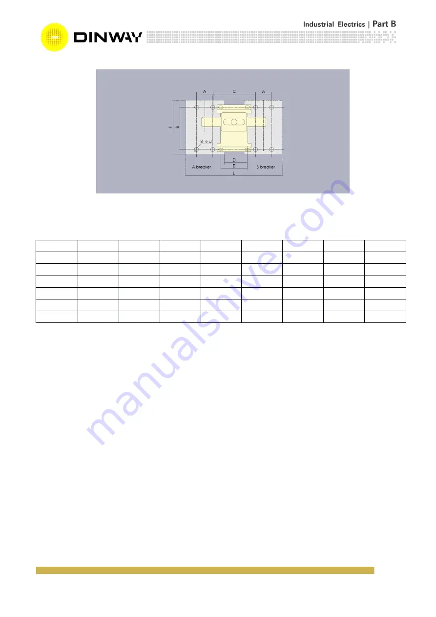
6. Outline and installation dimension

6.1 BAM8-63,100,225 fixed connection outline and installation dimension is shown in Fig. 15a and Table 10.

6.2 BAM8-400,630,800,1250 fixed connection outline and installation dimension is shown in Fig. 15b and Table 11.

6.3 BAM8 series rear connection and plug in connection outline and installation dimension is shown in Fig.16a, Fig.16b,

Fig.17a, Fig.17b, and Table 12.

Model

A

B

C

D

E

F

L

φd

BAM8-63

BAM8-100

30

129

90

30

90

155

210

4.5×6*

BAM8-225

35

126

100

30

100

165

240

5.5

BAM8-400

44

194

172

20

62

257

330

7

BAM8-630

58

200

175

48

62

270

412

7

BAM8-800

Содержание BAM8 Series

Страница 1: ...the company has a total 500 employees many products have also been certified by some international certificates such as CE CE CE CE CCC CCC CCC CCC PCT PCT PCT PCT and and and and KCT KCT KCT KCT SGS...

Страница 2: ...Moulded Moulded Moulded Case Case Case Case Circuit Circuit Circuit Circuit Breaker Breaker Breaker Breaker OPERATION OPERATION OPERATION OPERATION INSTRUCTION INSTRUCTION INSTRUCTION INSTRUCTION MAN...

Страница 3: ...into three kinds S type standard type H type higher type R type limit current type The product features small volume high breaking capacity and short arcing distance so that it is an ideal product for...

Страница 4: ...omponents N Pole is always at making status not makes and breaks with other three poles Without current release components N Pole makes with other three poles N pole first makes then breaks With curre...

Страница 5: ...unt release alarm contact 218 318 Auxiliary contact alarm contact 228 328 Under voltage release alarm contact 238 338 Shunt release auxiliary contact alarm contact 248 348 Shunt release under voltage...

Страница 6: ...00 35 10 17 5 5 BAM8 400S 4P In 2 BAM8 400H 3P 50 12 25 6 BAM8 400R 3P 70 15 35 7 5 BAM8 630S 3P 630 400 500 630 35 12 17 5 6 BAM8 630S 4P In 2 BAM8 630H 3P 50 13 25 6 5 BAM8 630R 3P 380 400 415 500 7...

Страница 7: ...emperature see Fig 1 Fig12 Characteristic Curve Fig 1 BAM8 63 10 32 BAM8 100 16 32 Fig 2 BAM8 63 40 63 BAM8 100 40 100 Characteristic Curve Characteristic Curve Fig 3 BAM8 63 10 32 BAM8 100 16 32 Fig...

Страница 8: ...B B B B 8 8 8 8 Fig 5 BAM8 225 Characteristic Curve Fig 6 BAM8 400 Characteristic Curve Fig 7 BAM8 225 Temperature compensation Curve Fig 8 BAM8 400 Temperature compensation Curve...

Страница 9: ...Internal accessory and external accessory of breaker are installed according to needs of users 5 1 Internal accessory of breaker 5 1 1 Shunt release The rated control voltage of the shunt release is A...

Страница 10: ...sed closed otherwise otherwise otherwise otherwise the the the the breaker breaker breaker breaker will will will will be be be be damaged damaged damaged damaged 5 1 3 Auxiliary contact Auxiliary con...

Страница 11: ...mechanism mechanism before before before before close close close close the the the the breaker breaker breaker breaker 5 2 2 Rotating handle operation mechanism See Fig 13 and Table 8 Fig 13 Table 8...

Страница 12: ...nection outline and installation dimension is shown in Fig 15b and Table 11 6 3 BAM8 series rear connection and plug in connection outline and installation dimension is shown in Fig 16a Fig 16b Fig 17...

Страница 13: ...0 50 F 22 22 22 22 22 22 G 14 14 175 175 23 23 G1 6 5 6 5 7 5 7 5 11 5 11 5 H 73 81 68 86 86 103 H1 90 98 5 86 102 110 127 H2 20 27 24 24 24 24 H3 4 4 4 4 4 4 H4 6 6 7 7 5 5 L 135 135 155 155 165 165...

Страница 14: ...97 F 62 65 65 65 66 52 78 G 28 30 5 40 44 44 45 G1 13 10 5 13 5 13 5 12 5 12 H 104 107 111 111 107 109 141 H1 155 150 160 160 148 156 202 H2 38 39 44 44 33 36 5 58 H3 6 6 6 6 4 5 5 16 5 H4 6 4 5 3 5 3...

Страница 15: ...B B B B 15 15 15 15 Fig 16a BAM8 63 100 225 rear connection Fig 16b BAM8 400 630 800 rear connection Fig 17a Installation hole of BAM8 series rear connection...

Страница 16: ...58 70 d 3 5 4 5 6 5 5 7 7 7 7 d1 12 5 16 5 16 5 d2 6 8 8 8 5 9 8 5 12 D 8 24 26 31 33 37 37 D1 8 16 20 33 37 37 37 H6 44 68 66 60 65 65 48 H7 66 108 110 120 120 125 125 H8 28 51 51 61 60 60 87 H9 38 6...

Страница 17: ...the wire must be fastened then the junction hole of the hoop is tightly connected with the terminal of breaker by screws If it is copper row the connecting board must fist be fixed on the breaker the...

Страница 18: ...fix breakdowns breakdowns breakdowns breakdowns Various defects of the breaker may take place in the process of operation For example fasteners are loose wires are not well connected and mechanism is...

Отзывы: