background image

CLM–36      

© 

Dinel, s.r.o.

13

10 .  s

etting

1.  Empty tank to the minimum level.

2.  By DIP switches on level meter set range

3)

 No. 2 (250 pF).

3.  Turn by screwdriver in 

trimmer  4  mA

 and set quiescent current of the level meter to  

  4 mA. Turning right wards (in clockwise) increase the current, turning left wards 


decrease the current. When is impossible to set required current to 4 mA, then switch  


DIP switches to the nearest higher range and set up of current 4 mA perform at this range. 

4.  Fill  the  tank  to  the  maximum  level.  When  it  is  impossible  fill  the  tank  to  the  maximum 


  state then we use some known (measurable) level and current for next setting 


calculate according to formula:


  I 

out = 4 + (0,16 x level in %)   [mA]

5.  If the output current is less than 20 mA (or the value of I out), set to the lowest  


range No. 1. by DIP switches  and continue to step 7. When the output current reaches  


20 mA

, 

continue on step 6.

6.  By DIP switches step wise switch to higher ranges till the current is greater then  

  20 mA (or calculated value I out

),  through  level  meter  then  flows  current  e.g.  21 mA

4)

.  


Trimmer 20 mA

 is still in basic position.

7.  Then set by 

trimmer 20 mA

 current of level meter to 20 mA (or to calculated value I out  


- see bellow).

8.  To reach a maximum accuracy is useful to check over the setting of  4 mA 


(compensation of initial capacity - quiescent current).

2)  Sensitivity - minimal capacity change of electrode to reach output range 4 ÷ 20 mA or 0 ÷10 V.

3)  Range = capacity of h activated electrode to reach output range 4 ÷ 20 mA or 0 ÷10 V.  


(For example.: uncoated electrode 1000 mm immersion in fuel: 20 pF + 30 pF,  


coated electrode 1000 mm immersion in water: 20 pF + 500 pF)

4)  In case of short of electrode  on housing  or  setting of a very  sensitive  range can caused to  current  


restriction of level meter on value max. 30 mA.

CURRENT OUTPUT 4 ... 20 mA

VOLTAGE OUTPUT 0 ... 10 V

1.  Empty tank to the minimum level.

2.  By DIP switches on level meter set range

3)

 No. 2 (250 pF).

3.  Turn by screwdriver in 

trimmer  0  V

 and set voltage output of the level meter to  

  0 V. Turning right wards (in clockwise) increase the voltage, turning left wards 


  decrease the voltage. When is impossible to set required voltage to 0 V, then switch  


DIP switches to the nearest higher range and set up of voltage 0 V perform at this range.

4.  Fill  the  tank  to  the  maximum  level.  When  it  is  impossible  fill  the  tank  to  the  maximum 


  state then we use some known (measurable) level and voltage for next setting 


calculate according to formula:


out = 0,1 x level in %   [V]

5.  If  the  output  voltage  is  less  than  10  V  (or  the  value  of  U  out),  set  to  the  lowest 


range No. 1. by DIP switches  and continue to step 7. When the output voltage reaches  


10 V,

continue on step 6.

Содержание CLM-36

Страница 1: ...s service manual and keep it for further use Service manual is for all types of level meters series CLM 36 Producer reserves the right to make changes without any previous announcement INSTRUCTIONS MA...

Страница 2: ......

Страница 3: ...and putting into operation 8 7 Installation 8 8 Electrical connection 11 9 Preparing of level meter for measuring 12 10 Setting 13 11 Use manipulation and maintenance 15 12 Order code 16 13 Correct sp...

Страница 4: ...described in this instruction manual have to be carried out only by trained personnel or an accredited person Warranty and post warranty service must be exclusively carried out by the manufacturer Im...

Страница 5: ...conductive liquids oils diesel petrol By means of reference tube the output signal does not depend on the dimensions and shapes of a vessel Max length 3m CLM 36_ 22 With fully FEP coated rod electrode...

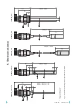
Страница 6: ...CLM 36 Dinel s r o 5 CLM 36_ 30 4 D imensions drawings CLM 36_ 10 11 12 CLM 36_ 20 22 CLM 36_ 32 CLM 36_ 40 Thread Threads M36x2 G1 Fig 1 Dimensional drawings of the capacitive level meters...

Страница 7: ...CLM 36_ 31 Rope electrode Wall of container KV 31 PR 31 Spring Anchor with spherical joint Anchor welding cylinder KV 31 or Dust tight bushing PR 31 see accessories Housing with Tri clamp coupling Fi...

Страница 8: ...reference tube CLM 36_ 20 22 or by reference electrode CLM 36_ 40 In the tank with straight wall for example vertical cylinder and with the sensor placed parallely with the wall capacity change is lin...

Страница 9: ...s by level meter without reference tube is necessary to connect grounding screw at housing with auxiliary electrode which is fixed by the appropriate method to the outer casing of vessels or at inner...

Страница 10: ...36_ 30 32 connection to the armouring E The length of electrode the lower end of the electrode has to be dipped min 20 mm below the lowest measured level h The distance from the bottom min 100 mm a T...

Страница 11: ...the lower end of the electrodes have to be dipped min 20 mm below the lowest measured level h The distance from the bottom min 30 mm a The distance from the wall min ca E 20 Fig 7 Installation of rop...

Страница 12: ...ut 0 10 V Tigh ten the terminals firmly 5 Push the terminals back into the connector so that the terminal no 3 is oriented toward the cable entry Tighten the cable gland 6 Check the seal on the connec...

Страница 13: ...e trimmers are without backstops approx 15 turns ADJUSTMENT ELEMENTS OF LEVEL METER Fig 13 The top view on the internal electronic module with current outptu variant I DIP switches for range select tr...

Страница 14: ...seful to check over the setting of 4 mA compensation of initial capacity quiescent current 2 Sensitivity minimal capacity change of electrode to reach output range 4 20 mA or 0 10 V 3 Range capacity o...

Страница 15: ...y 2 S Range 3 R Position of DIP switch 1 1 20 pF 70 pF 2 30 pF 250 pF 3 50 pF 600 pF 4 100 pF 1 200 pF 5 150 pF 3 000 pF 6 300 pF 7 000 pF 7 500 pF 18 000 pF 8 1 000 pF 36 000 pF 1 Range No 1 70 pF is...

Страница 16: ...l meter and press down by clamping ring attention that contact pin will be a little open before insertion and contact springs were not pressed under level of electronic casing 5 Check placing of black...

Страница 17: ...lectrode with anchor max 20 m 32 Fully coated rope electrode and weight FEP PTFE 40 Two fully coated St steel rod electrode FEP max 2 m CLM 36 E Length electrode in mm Process connection M thread M36x...

Страница 18: ...ecial conditions for safe use of variant CLM 70Xi Equipment is designed to be connected to isolating repeater IRU 420 If other approved apparatus is used which output parameters comply with above ment...

Страница 19: ...Ser No ______ from the left production year serial production number Supply voltage Ui 9 36 V DC Output current range I 4 20 mA Ambient temperature range ta 40 85 C Protection class IP 65 IP 67 Compli...

Страница 20: ...n Czech Republic www dinel cz dinel dinel cz U 0 10 V out U 16 36 V i Dinel U 3 2 Uout i 0 V V t 40 85 C a IP65 IP67 Dinel s r o Zl n Czech Republic www dinel cz dinel dinel cz U 0 5 V out U 11 36 V i...

Страница 21: ...7A IP67 Housing IP65 Connector IP67 Maximal load serial resistance for current output U 24 V Rmax 750 Minimal load resistance for voltage output Rmin 1 k Maximum tensile strength of the rope electrod...

Страница 22: ...nd 20 housing zone 1 and 21 U sed M aterials Sensor part Variants Standard material Optional on request Housing All types except CLM 36_ 40 CLM 36_ 40 St Steel W Nr 1 4301 AISI 304 PTFE St Steel W Nr...

Страница 23: ...incl KV 31 40 C 105 C 40 C 75 C 40 C 75 C CLM 36Xi 32 40 C 105 C 40 C 75 C 40 C 75 C CLM 36NT 10 20 40 C 300 C 40 C 200 C 40 C 85 C CLM 36NT 11 12 22 40 C 200 C 40 C 200 C 40 C 85 C CLM 36NT 30 40 C...

Страница 24: ...CLM 36N 32 1 MPa 0 5 MPa CLM 36N 40 0 1 MPa 0 1 MPa CLM 36Xi 10 20 7 MPa 5 MPa CLM 36Xi 11 12 22 4 MPa 2 MPa CLM 36Xi 30 7 MPa 5 MPa CLM 36Xi 31 CLM 36Xi 32 1 MPa 0 5 MPa CLM 36NT 10 20 7 MPa 5 MPa 3...

Страница 25: ...e 47 Grains 3 0 5 0 Hardened textile 2 6 Hexane 1 9 Materi l r Chloroforme 4 81 Ice 3 1 Liquefied air 1 5 Liquefied CO2 1 6 Liquefied chlore 2 0 Liquefied propan 1 6 1 9 Marble 9 3 11 6 Methanol 32 7...

Страница 26: ...4 5 Resin epoxy 2 5 8 0 Resin melamine 4 7 10 2 Resin phenolic 4 0 12 0 Resin polyester 2 8 8 1 Resin styrene 2 3 3 4 Resin ureal 5 0 8 0 Rubber 2 0 6 0 Sand 3 0 5 0 Silicon caoutchouc 2 8 3 3 Succin...

Страница 27: ...26 Dinel s r o CLM 36...

Страница 28: ...y 249 760 01 Zl n Czech Republic Tel 420 577 002 003 Fax 420 577 002 007 E mail sale dinel cz www dinel cz The lastest version of this instruction manual can be found at www dinel cz Version industria...

Отзывы: