Instruction Manual
SAFELINE VARIO Diagnostics
18
2 Rack-Diagnostics
The upper area contains buttons. Left-click leads to further status information window.
Status information about timer, counters, safety mats, copiers, cams,
analog terminals, analog-input-comparator, safe braking test
see chapter “Information to…“
DNCO-Tables
See chapter „Tables“
The lower level contains information windows to hardware
Current and voltage at the terminals A1, O1 and O2 device temperature
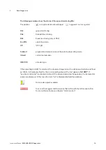
The following additional area appears if the application contains the function speed monitoring.
(Fig. 2-6)
Fig.
2-6
SMx
Configured speed monitoring. Selection with a left click.
The corresponding field is blue.
Initiators
encoder type
Setpoint
Programmed setpoint value of he selected mode
Actual
current actual value
value
If the operating mode MT is selected, the observed target value for each speed module is defined
as infinite. In the display field for the corresponding setpoint the text appears „
NO LIMIT
“.
If "position monitoring" is activated, instead of the desired and actual frequencies, the incremental
values are displayed. In this case the term "ink" is displayed behind the numbers.

