


6
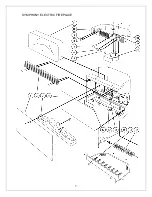
SYMPHONY ELECTRIC FIREPLACE
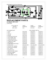
RREPLACEMENT PARTS
SF SERIES FIREPLACES
SYMPHONY
\CATALOGUE NO.
SF5598
SF5598
SF5598
PART NO.
6900240459
6900240459
6900240459
MOD. LEVEL
None
Mod A & B
Mod C
REPLACEMENT PART
REPLACEMENT PART NO.
1. GLASS
6900100500
6900100500
6900100500
2. GRILL
6900080159
6900080159
6900080159
3. LOG SET
0437960100
0437960100
0437960100
4. MIRROR
6900100300
6900100300
6900100300
5. POWER ON/OFF SWITCH
2800070100
2800070100
2800070200
6. LIGHT DIMMER KNOB
8800000100
8800000100
8800000800
7. FLAME SPEED KNOB
8800000200
8800000200
8800000200
8. HEATER ON/OFF SWITCH
2800070200
2800070200
2800070200
9. THERMOSTAT KNOB
8800000300
8800000300
8800000300
10.THERMOSTAT
2300150100
2300150100
2300150100
11.FLAME PROJECTION PANEL
0437970100
0437970100
0437970100
12.LIGHT BLOCK
NOT AVAILABLE
NOT AVAILABLE
NOT AVAILABLE
13.LOWER LIGHT HARNESS
2500090100
2500090100
2500090100
14.UPPER LIGHT HARNESS
2500080100
2500080100
2500080100
15.D.C. MOTOR
6900140100
2000150100
2000150100
16.SUPPORT FOOT
8800090100
8800090100
8800090100
17.REFLECTOR ROTISSERIE
6900190300
6900190400
6900190400
18.HEATER ASSEMBLY
2200290600
2200290600
2200290600
19.LIGHT DIMMER
2800020100
2800020100
2800020100
20.FLAME SPEED CONTROL
3000180300
3000180300
3000180300
Содержание SYMPHONY SF5598
Страница 1: ...SYMPHONY MODEL SF5598 PARTS SERVICE MANUAL...
Страница 5: ...5 SYMPHONY ELECTRIC FIREPLACE...


