EN-6 453322.66.16 ·10/14/B
www.dimplex.de/en
E
n
g
lis
h
RTV 101EO, RTF 101EO
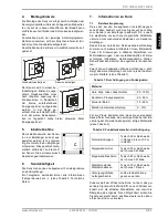
Mounting base plate Mounting frame
The sensor is supplied in an
operational status. Probably,
the internal solar energy stor-
age must be reloaded after a
longer storage of the radio
sensors in darkness. In prin-
ciple, the reloading process is
done automatically during the
first operating hours in day-
light. For this purpose, please refer to the remarks “so-
lar energy storage”.
5.
Installation
In order to assure a correct
evaluation of the measuring
values by the receiver, it is nec-
essary to have the devices
learned by the receiver. This is
done automatically by means of
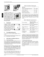
a “learn button” (C) at the sen-
sor. The learn button must
press for 5 seconds.
6.
Transmitting Frequency
The sensors send time controlled telegrams to the re-
ceiver.
A telegram includes all information (temperature value
etc….). (see table 3 Technical Data)
7.
Information on Wireless Sensors
7.1 Transmission Range
As the radio signals are electromagnetic waves, the
signal is damped on its way from the sender to the re-
ceiver. That is to say, the electrical as well as the mag-
netic field strength is removed inversely of the distance
between sender to receiver.
Beside these natural transmission range limits, further
interferences have to be considered: Metallic parts,
e.g. reinforcements in walls, metallized foils of thermal
insulations or metallized heat-absorbing glass, are re-
flecting electromagnetic waves. Thus, a so-called radio
shadow is built up behind these parts.
It is true that radio waves can penetrate walls, but
thereby the damping attenuation is even more in-
creased than by a propagation in the free field (table1).
For the practice, this means, that the building material
used in a building is of paramount importance for the
evaluation of the transmitting range. For an evaluation
of the environment, some guide values are listed
(table2):
In addition, the angle with which the signal sent arrives
at the wall is of great importance. Depending on the an-
gle, the effective wall strength and thus the damping at-
tenuation of the signal changes. If possible, the signals
should run vertically through the walling. Walling re-
cesses should be avoided.
7.2 Other Interference Sources
Devices, that also operate with high-frequency signals,
e.g. computer, auido-/video systems, electronical
transformers and ballasts etc. are also considered as
an interference source.
The minimum distance to such devices should amount
to 0,5 m.
A
B
RTV1
01EO
Learn
c
Table 1: Penetration of radio signals
Material
Wood, gypsum,glass uncoated
90...100%
Brick,pressboard
65...95%
Reinforced concrete
10...90%
Metall, alumium pasting
0...10%
Table 2: Radio path range/-penetration:
Visual contacts
Typ. 30 m range in
passages, corridors, up to
100m in halls
Rigypsum walls/wood
Typ. 30 m range through
max. 5 walls
Brick wall/Gas con-
crete
Typ. 20 m range through
max. 3 walls
Reinforced concrete/-
ceilings
Typ. 10 m range through
max. 1 ceiling
Supply blocks
Lift shafts
should be seen as a com-
partmentalisation


