


8 www.dimplex.com
maintenance to reduce the risk of electric shock or damage
to persons.
!
NOTE:
Ensure that all of the components that
contain water have been emptied before performing any
maintenance.
1. Disconnect and remove the log set from the unit and
put it in a safe place.
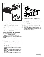
2. Remove the 4 screws that secure the front grill to the
cassette housing. (Figure 4)
3. Locate the defective switch and disconnect the wiring
connections noting their original locations.
!
NOTE:
A flat head screwdriver can be used to gently
pry between the end of the connector and the switch to
release the wires.
4. Depress the retainer clips on the rear of the switch and
push the switch out through the opening.
5. Properly orient and insert the new switch and connect
all of the wiring.
6. Re-assemble the remainder of the cassette in reverse
order from the instructions above.
THERMOSTAT REPLACEMENT
Tools Required:
Phillips head screwdriver
Flat Head Screwdriver
WARNING:
Disconnect power before attempting any
maintenance to reduce the risk of electric shock or damage
to persons.
!
NOTE:
Ensure that all of the components that
contain water have been emptied before performing any
maintenance.
1. Disconnect and remove the log set from the unit and
put it in a safe place.
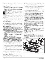
2. From the front of the unit, remove the top cover and the
water tank from the inside of the unit. (Figure 3)
3. Inside of the unit remove the two screws that secure
the cassette assembly to the chassis.
4. Lift the cassette assembly out of the unit.
5. Remove the 4 screws that secure the front grill to the
cassette housing. (Figure 4)
6. Remove the knob off of the thermostat, by gently lifting
the bottom forward and pulling down.
7. Depress the retainer clips on either side of the thermo-
stat to slide it out of the assembly.
8. Disconnect the wiring connections noting their original
locations.
!
NOTE:
A flat head screwdriver can be used to gently
pry between the end of the connector and the switch to
release the wires.
9. Install the knob onto the new thermostat and slide the
thermostat back into the assembly ensuring that it has
“clicked” into place.
10. Re-assemble the remainder of the cassette in reverse
order from the instructions above.
POTENTIOMETER REPLACEMENT
Tools Required:
Phillips head screwdriver
Flat Head Screwdriver
3/8” (10mm) Wrench
WARNING:
Disconnect power before attempting any
maintenance to reduce the risk of electric shock or damage
to persons.
!
NOTE:
Ensure that all of the components that
contain water have been emptied before performing any
maintenance.
1. Disconnect and remove the log set from the unit and
put it in a safe place.
2. From the front of the unit, remove the top cover and the
water tank from the inside of the unit. (Figure 3)
3. Inside of the unit remove the two screws that secure
the cassette assembly to the chassis.
4. Lift the cassette assembly out of the unit.
5. Remove the 4 screws that secure the front grill to the
cassette housing. (Figure 4)
6. Turn the unit so that the underside of the potentiometer
can be seen.
7. Loosen the securing nut, to allow the potentiometers
slide out.
8. Disconnect the wiring connections noting their original
locations.
!
NOTE:
A flat head screwdriver can be used to gently
pry between the end of the connector and the switch to
release the wires.
9. Slide the potentiometer back into the assembly and
tighten the securing nut.
10. Re-assemble the remainder of the cassette in reverse
order from the instructions above.
POWER CORD / RECEPTACLE
REPLACEMENT
Tools Required:
Phillips head screwdriver
Flat head screwdriver
WARNING:
Disconnect power before attempting any
maintenance to reduce the risk of electric shock or damage
to persons.
!
NOTE:
Ensure that all of the components that
contain water have been emptied before performing any
maintenance.
1. Disconnect and remove the log set from the unit and
put it in a safe place.
2. Remove the back panel off of the unit, there are 9
screws around the outside and 2 near the bottom
middle.
3. From the front of the unit, remove the top cover and the
water tank from the inside of the unit. (Figure 3)
4. Inside of the unit remove the two screws that secure
the cassette assembly to the chassis.
5. Lift the cassette assembly out of the unit.


