Dimplex OS2527GB Скачать руководство пользователя страница 3

3

D . Flame Intensity Control

Adjusts the intensity of the flame and smoke effect when the 

heater has been activated. 
Turning the control knob clockwise decreases the intensity 

of the flame and smoke effect. Turning the control counter-

clockwise will increase the flame and smoke effect.

!

NOTE: 

Give the flame generator some time to react to 

changes you may make on the flame control knob.

!

NOTE: 

When the water tank is empty the unit will turn 

off after 30 seconds. See instructions under Maintenance 

Section for refilling tank. When this procedure is complete, 

the main lamps will illuminate but it will take 30 seconds 

before the flames return. 

Resetting the Temperature Cutoff Switch

Should the heater overheat, an automatic cut out will turn 

the heater off and it will not come back on without being 

reset. It can be reset by switching the On/ Off Switch to Off 

and waiting 10 minutes before switching the unit back on.

 CAUTION:

 If you need to continuously reset the heater, 

unplug the unit and call Dimplex North America Limited at 

1-888-346-7539 for technical support. Please have your 

model and serial number ready when calling.

Remote Control


The On/Off Switch must be in the ‘ON’ 

( I )

 position in order 

for the remote control to operate (Figure 5A). There are 3 

buttons on the remote control. (Figure 2) 

!

NOTE: 

To operate correctly the remote control must be 

pointed towards the remote control sensor.
The remote control functions are as follows:


Press once to turn on Flame effect only.  This will be 

indicated by one beep.


Press once to turn on Full heat and Flame effect.  This 

will be indicated by two beeps.


Standby - This will be indicated by one beep.

!

NOTE: 

Once the mist has been activated, the unit will 

have to be turned Off, using either the momentary button, 

OPERATION

Figure 1

 WARNING:

 This electric firebox must be properly in-

stalled before it is used.

!

 NOTE: 

When the unit is used in an environment where 

background noise is very low, it may be possible to hear a 

sound which is related to the operation of the flame effect. 

This is normal and should not be a cause for concern. 

!

 NOTE:  

Always ensure that the appliance is in a level 

position.

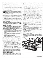
The manual controls for the unit are located below the con-

trol cover in front of the log grate (Figure 1).

A . On/Off Switch 

Supplies power to the unit.

B . Thermostat Control

To adjust the temperature to your individual requirements, 

turn the thermostat control clockwise all the way to turn on 

the heater. When the room reaches the desired tempera-

ture, turn the thermostat knob counter-clockwise until you 

hear a click. Leave thermostat in this position to maintain 

the room temperature at this setting. For additional heat, 

turn clockwise until you hear the click again and the heater 

will turn on.

C . Mode Selector Switch


Press 

 once to turn on the flame effect. This will be 

indicated by an audible “beep”. Although the lights turn on 

immediately it will take 30 seconds before the flame effect 

starts.
•  Press again to give flame effect and full heat. This will 

be indicated by two “beeps”.

•  Press again to return to flame effect only. This will be 

indicated by one “beep”.

•  Press   to put fire in to standby mode. This will be 

indicated by one “beep”.

Figure 2

D

A

C

B

Remote Control 

Sensor

Battery Cover

Standby 

Button

Flame

Button

Heat

Button

Содержание OS2527GB

Страница 1: ...h America Limited Dimplex North America Limited 1367 Industrial Road Cambridge ON Canada N3H 4W3 1 888 346 7539 www dimplex com REV PCN DATE 00 15 NOV 16 IMPORTANT SAFETY INFORMATION Always read this manual first before attempting to service this cassette For your safety always comply with all warnings and safety instructions contained in this manual to prevent personal injury or prop erty damage ...

Страница 2: ... if not carefully followed will expose the user to the risk of fire serious injury or death Operation 3 Maintenance 4 Exploded Parts Diagram 5 Replacement Parts List 5 Wiring Diagram 6 Remote Control Receiver Replacement 7 Power Board Replacement 7 Switch Replacement 7 Thermostat Replacement 8 Potentiometer Replacement 8 Power Cord Receptacle Replacement 8 Fuse Fuse Assembly Replacement 9 Light As...

Страница 3: ...urn on Full heat and Flame effect This will be indicated by two beeps Standby This will be indicated by one beep NOTE Once the mist has been activated the unit will have to be turned Off using either the momentary button OPERATION Figure 1 WARNING This electric firebox must be properly in stalled before it is used NOTE When the unit is used in an environment where background noise is very low it m...

Страница 4: ...ch lamp needs to be changed 3 Turn the unit off and unplug the unit 4 Leave the appliance for 20 minutes to allow the lamps to cool down before removing them 5 Remove the defective bulb by gently lifting vertically and disengaging the pins from the lamp holder NOTE Replacement light bulbs can be obtained by contacting Dimplex Customer Service at 1 888 346 7539 6 Carefully insert the two pins of th...

Страница 5: ...bly 9600540100RP 11 Fan Filter 8600300100RP 12 Transducer 3800040100RP 13 Power Cord 9600740100RP 14 Receptacle Cord 9600780100RP 15 On Off Switch 9600383500RP 16 3 Position Switch 9600383600RP 17 Transformers 9600690100RP 18 Potentiometer 9600640100RP 19 Thermostat Assembly 9600620100RP 20 Control Knob 9600630200RP 21 Power Board 9600590100RP 22 IR Receiver with Lens 9600600200RP 23 Light Bulbs P...

Страница 6: ...om WIRING DIAGRAM LINE IN MOTOR ELEMENT THERMAL CUTOUT PCB ELEMENT THERMOSTAT TRANSFORMER TRANSFORMER LIGHTS LIGHTS POWER BOARD SELECTOR SWITCH POTENTOMETER IR SENSOR TRANSDUCER FAN MOTOR N1 N2 3 4 5 6 NEUTRAL GROUND ...

Страница 7: ... secure the cassette assembly to the chassis 4 Lift the cassette assembly out of the unit 5 Remove the 4 screws that secure the front grill to the cassette housing Figure 4 6 Remove the 4 screws around the power board attach ing it to the unit 7 Transfer the wire connectors from the terminals on the original board to the same location on the replacement board Figure 4 Front Grille Transformers Pow...

Страница 8: ...ew thermostat and slide the thermostat back into the assembly ensuring that it has clicked into place 10 Re assemble the remainder of the cassette in reverse order from the instructions above POTENTIOMETER REPLACEMENT Tools Required Phillips head screwdriver Flat Head Screwdriver 3 8 10mm Wrench WARNING Disconnect power before attempting any maintenance to reduce the risk of electric shock or dama...

Страница 9: ...ewdriver Flat Head Screwdriver WARNING Disconnect power before attempting any maintenance to reduce the risk of electric shock or damage to persons NOTE Ensure that all of the components that contain water have been emptied before performing any maintenance 1 Disconnect and remove the log set from the unit and put it in a safe place 2 From the front of the unit remove the top cover and the water t...

Страница 10: ...he unit and put it in a safe place 2 Lay the unit on it s back to access the heater assembly area 3 Remove the 4 screws that secure the assembly to the stove Figure 7 4 Allow the assembly to separate from the stove by gen tly pulling the cord out of the opening in the bottom of the stove 5 Remove the 2 screws on the top of the assembly 2 on the bottom on either side and 2 on either side of the hea...

Страница 11: ...t Add 1 8 tsp of table salt to water reservoir to introduce electrolytes only repeat when mist is not being produced correctly Check that the fan is operating correctly Replace fan assembly Ensure that the air filter is clean and dry Cord is located over emitter on transducer Relocate cord so that mist is free to rise off of transducer Defective Transducer Replace Transducer The flame effect is to...

Страница 12: ...Fuse Heater is turning off after a couple of minutes of operation Build up of dirt dust in Heater Assembly Ensure that exterior intake louvers and housing cavity are free of dirt dust Defective Heater Assembly Replace Heater Assembly Heater emits an odor Normal Operation Normal operation is when the heater emits an odor for a brief period after the heater is initially turned on The heater is burni...

Отзывы: