


5
Level 1:
The fl ame effect is turned on and the fi rst red indicator light is activated.
Level 2:
The fl ame effect remains on, and the Purifi re
TM
is activated. The fi rst and second red
indicator lights are activated.
Level 3:
The fl ame effect remains on, the heater is activated, and all three red indicator lights are
activated.
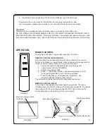
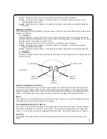
MANUAL CONTROLS
The fi replace can also be controlled in a similar manner to the remote control with switches located on the
fi replace (FIGURE 6).
A.
On
Switch
Operates
fi replace in the same manner as the remote control transmitter. Pressing this button has
the same effect as the ON button on the remote control. Pressing once to the activates Level 1, twice
activates Level 2, three times activates Level 3.
Level 1:
The fl ame effect is turned on and the fi rst red indicator light is activated.
Level 2:
The fl ame effect remains on, and the Purifi re
TM
is activated. The fi rst and second red
indicator lights are activated.
Level 3:
The fl ame effect remains on, the heater is activated, and all three red indicator lights are
activated.
B. Off Switch
Pressing this button has the same effect as the OFF button on the remote control. Pressing once will
shut the unit off.
FIGURE 6
B. OFF Switch
A. ON Switch
Level 2
Indicator
Level 3
Indicator
Level 1
Indicator
HEATER THERMOSTAT CONTROL
To adjust the temperature to your individual requirements, turn the thermostat control clockwise all the
way to turn on the heater. When the room reaches the desired temperature, turn the thermostat knob
counter clockwise until you hear a click. Leave in this position to maintain the room temperature at this
setting. For additional heat, turn clockwise until you hear the click again and the heater will turn on
NOTE
The heater may emit a slight harmless odor when fi rst used. This odor is a normal condition caused by
initial heating of internal parts and will not occur again.
THE TEMPERATURE CUTOUT SWITCH
The heater on this fi replace is protected with a safety device to prevent overheating. Should the heater
overheat, an automatic cut out will turn the heater off. The heater will re-activate once the heater has
cooled. The overheat cutout may be triggered if the fi lter is dirty. Follow fi lter maintenance on Page 7.
CAUTION
If the heater continuously resets, disconnect the power at the main service panel and call your local
dealer.
Содержание LAGUNA LAGFB2
Страница 1: ...LAGUNA FIREBOX LAGFB2 08 51849 0 ISS1 UK ...


