background image

www.dimplex.de/en                                  459462.66.01 · 10/14/B

EN-37

E

n

g

li

s

h

FSR 15-35 / FSR 15-35 GS / FSR 15-35 GW

7 LR SES Charge Controller

7.1 Operation using a standard charge control system

DC control signal: 0.91 to 1.43 V DC
Connect charge control cable to terminals A1+ and A2- on the
storage heater.

ACHTUNG!

Ensure  you  connect  the  cables  to  the  terminals  with  the
correct polarity!

AC control signal 230V AC

Connect  charge  control  cable to  terminals  A1~  and  A2~  on
the storage heater.

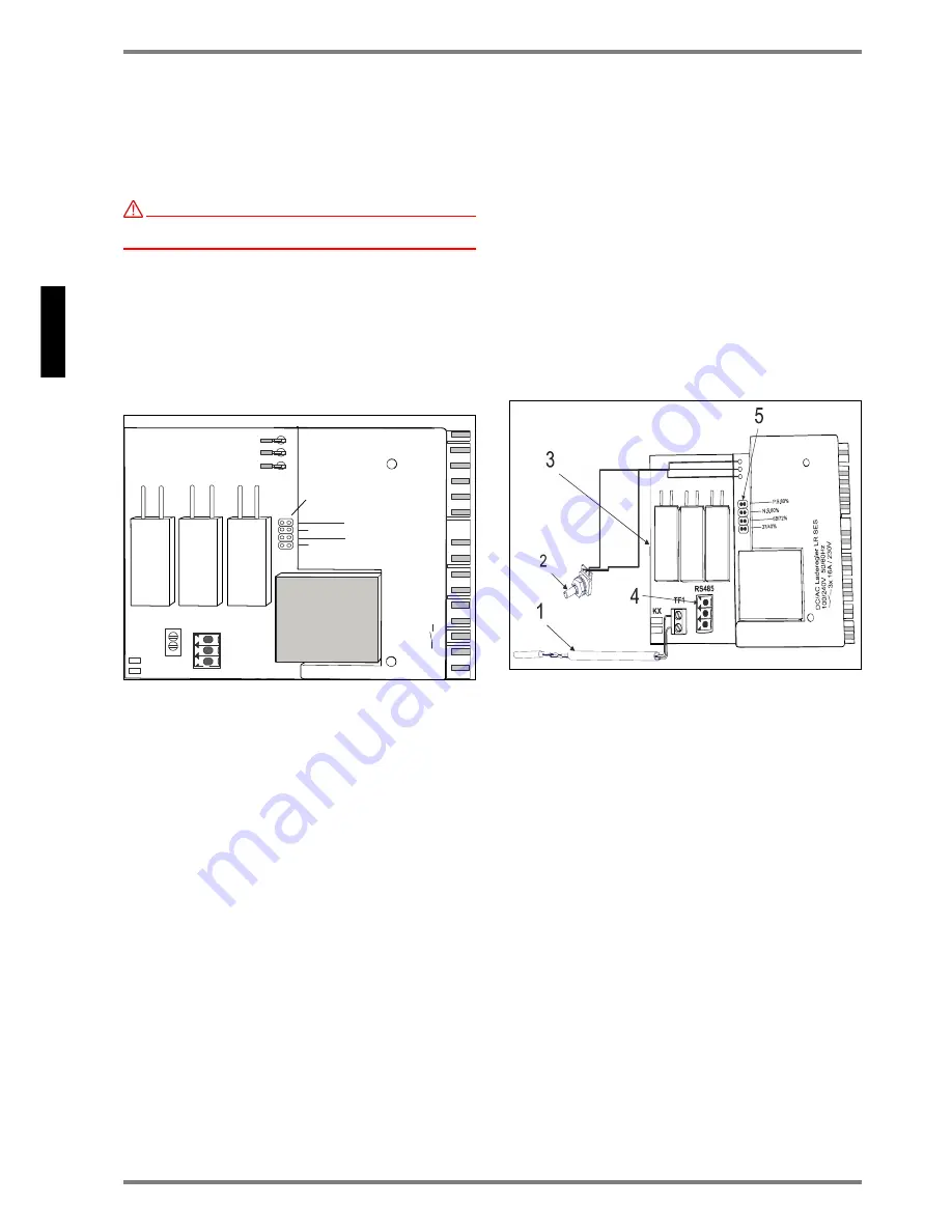
On ED system charge control systems, the storage heater's
charge  controller can be  operated at  80%, 72%, 68%, 40%
and 37%. The factory setting is for 80% ED systems.

If the storage heater is operated on other ED systems, then
the program jumper (A) must be plugged in at the appropriate
position.

Fig. 34: Charge regulator with program jumper (A) ED signal

7.2 Setting - reaction to fault

The  factory  setting  is  for  the  storage  heater  to  be  pro-
grammed  for  "positive  reaction  to  fault"  (known  also  by  its
German abbreviation, "P.S."). This means that, if the control
current fails, e.g. due to a defect in the charging control de-
vice, the equipment charges up to maximum heat storage. 

If  charging  is  not  required,  if  this  fault  occurs,  the  program
jumper (B) on the charge regulator can be set to "negative re-
action to fault"(known also by its German abbreviation, "N.S.").

Programming to set a "negative reaction to fault" can only be
carried out during operation on suitable charging control de-
vices. In addition, an 80% ED signal is necessary in the case
of AC charging control devices.

7.3 Operation on SES Smart Eco System

Quantum storage heaters can also be controlled using an in-
telligent home automation "Smart Eco System". This also en-
ables  the  system  to  be  operated  with  minimum  power  con-
sumption. 

The  following  components  are  necessary  in  this  case:  an
SES KM1 communication module for each storage heater, a
special radio room temperature gauge (RT.101EO) per room,
and an FG 101 EO external sensor and SES ZE central unit
per system.

For more detailed information, please refer to the relevant op-
erating instructions.

7.4 Performing a functional test on the charge con-

troller

Description

The  charge controller integrated in  the storage  heater is  an
electronic  two-point  regulator  which  switches  230V~  to  the
heating elements, depending on the:

core temperature,

charging control signal (to A1+ and A2- or A1~ and A2~),

load activation (to L-SH, N-SH), and

the setting on the potentiometer,

via the 3 relay outputs.

The core temperature (heat storage) is recorded using a plat-
inum residual heat gauge. The residual heat gauge's resist-
ance value at room temperature equals: R20°C = 107 Ohm.

Fig. 35:Charge controller components

1 - Residual heat gauge                      

2 - Intensity setter (potentiometer)

3 - Switch relay for heating elements       

4 - Service port          

5 - ED signal program jumper

Prerequisites

A charge control cable must not be connected to the ter-
minals A1+ and A2- or A1 and A2~.

The  functional  test  must  be  performed  on  the  storage
heater when it is cold.

The program jumper on the charge controller must be set
to "PS" 80% (factory setting).

Mains  voltage  must  be  present  on  terminals  "L-R,N-R"
and  "L-SH,  N-SH"  (terminal  screws  must  be  tightened
up). 

If an SES KM1 communication module is present, it must
be unplugged.

Functional test

Turn the potentiometer anticlockwise until it stops on the left:

The heating elements must not be affected by the 
controls!

Turn the potentiometer clockwise until it stops on the right:

The heating elements must be affected by the controls!

37/40%

 TF1

 KX

 R

S

4

8

5

68/72%

P.S.80%

N.S.80%

D

C

/A

C

 L

a

d

e

re

g

le

L

R

 S

E

S

1

0

0

/2

4

0

V


5

0

/6

0

H

z


3

x

 1

6

A

 /

 2

3

0

V

A

Содержание FSR 15...35

Страница 1: ...sanweisung Installation and instruction manual Quantum storage heater Classic Slim Line Design Slim Line Bestell Nr Order no 459462 66 01 10 14 B Wärmespeicher Quantum Classic Slim Line Design Slim Line FSR 15 35 FSR 15 35 GS FSR 15 35 GW ...

Страница 2: ...nter Mängel geschied dadurch dass die mangelhaften Teile unentgeldlich nach unserer Wahl instantgesetzt oder durch einwandfreie Teile ersetzt werden Durch Art oder Ort des Einsatzes des Gerätes bedingte au ßergewöhnliche Kosten der Mängelbeseitigung werden nicht über nommen Der freie Gerätezugang muss durch den Endabnehmer gestellt werden Ausgebaute Teile die wir zurücknehmen gehen in unser Eigent...

Страница 3: ...gelieferten Wandhalterungen DE 9 4 2 Bohrschablone für Bodenaufstellung mit Zubehörkonsole WKO18 DE 10 5 Montage DE 11 5 1 Gerätedemontage DE 11 5 2 Geräteaufstellung DE 12 5 3 Gerätemontage DE 13 5 4 Elektrischer Anschluss DE 15 5 5 Inbetriebnahme DE 17 5 6 Erneute Montage DE 17 6 Außerbetriebnahme und Entsorgung DE 17 6 1 Außerbetriebnahme DE 17 6 2 Entsorgung DE 17 7 Aufladeregler LR SES DE 18 ...

Страница 4: ...de in das Gerät einführen oder in Berührung bringen Dies könnte zu Funktionsstö rungen oder zum Entzünden der Gegenstände füh ren Hinter den Wärmespeicher gefallene Gegenstände sind sofort zu entfernen Sicherstellen dass Kleinkinder oder gebrechliche Menschen die Geräteflächen insbesondere das Luftaustrittsgitter nicht berühren Es ist unbedingt darauf zu achten dass keine Ge genstände wie z B Vorh...

Страница 5: ...peicher bestimmt Der Einsteller für Aufladung am Wärmespeicher wird bei dieser Betriebsweise auf maximale Aufladung im Uhrzeigersinn auf Rechtsanschlag gestellt Werks einstellung 2 4 Aufladung manuell Handbetrieb Wenn die Aufladung am Gerät manuell geregelt wer den soll wird der Drehknopf für Aufladung auf die Ach se des Einstellers aufgesteckt Dazu die Abdeckkappe an der rechten Seitenwand des Wä...

Страница 6: ...en entfernt werden Unterlegplatten Sonderzubehör müssen verwendet werden bei wärmeempfindlichen Bodenbelägen die Tem peraturen von 80 C nicht zuverlässig widerstehen wenn zu erwarten ist dass die Standfüße in den Boden einsinken so dass der Luftaustausch unter dem Wärmespeicher behindert wird Der günstigste Aufstellungsort ist unter einem Fenster Werden 2 Wärmespeicher nebeneinander aufgestellt so...

Страница 7: ...SR 15 35 FSR 15 35 GS FSR 15 35 GW 3 2 1 Aufstellmöglichkeiten Abb 6 Wandmontage mit mitgelieferten Wandhaltern Abb 7 Bodenmontage mit mitgelieferten Wandhaltern Abb 8 Wand Bodenmontage mit Zubehörkonsolen WKO18 Abb 9 Mindestabstände in der Wandnische ...

Страница 8: ...ww dimplex de Deutsch FSR 15 35 FSR 15 35 GS FSR 15 35 GW 3 3 Maße der Leitungseinführung Abb 10 Ansicht Frontseite Typ Maß A FSR 15 GS GW 808 mm FSR 20 GS GW 958 mm FSR 25 GS GW 1108 mm FSR 30 GS GW 1258 mm FSR 35 GS GW 1408 mm ...

Страница 9: ...n ACHTUNG Mauerwerkstragfähigkeit prüfen Abb 11 Bohrschablone für Bodenaufstellung oder Wandmontage mit Standard Wandhaltern Gerät von der Frontseite gese hen 1 Außenkante an der Wand markieren Einhängehilfe 2 Befestigungsloch für Sicherungsschraube Durchmesser 8mm Tiefe 80mm 3 Befestigungslöcher für Wandhalter Durchmesser 10mm Tiefe min 130mm 4 Wandhalterung 5 Kabeleinführungsöffnungen ...

Страница 10: ... Abb 12 Bohrschablone für Wand Bodenaufstellung mit Zubehörsatz Konsole WKO 18 Gerät von der Frontseite gesehen 1 Außenkante an der Wand markieren Einhängehilfe 2 Befestigungsloch für Sicherungsschraube Durchmesser 8mm Tiefe 80mm 3 Befestigungslöcher für Wandhalter Durchmesser 10mm Tiefe min 130mm 4 Zubehör Konsole WKO18 5 Kabeleinführungsöffnungen ...

Страница 11: ...n Wandanschlussleisten an der Geräterückwand anschrauben Obere Wandanschlussleiste an den beiden seitlichen Wandanschlussleisten anschrau ben Abb 15 Schrauben der beiden Seitenwände entfernen A Die Seitenwände nach unten schieben 1 und ausschwen ken 2 Nach Abnehmen der Seitenwände die Befestigungs schrauben B des Frontgitter lösen und das Frontgitter ent fernen Danach die Befestigungsschrauben C f...

Страница 12: ...stallateur eine geeignete Wandbefestigung gewählt werden Abb 17 Bodenmontage Hierzu die mitgelieferten Wandhalter nach Bohrschablone Abb 11 anbringen Abb 18 Wandmontage Hierzu die mitgelieferten Wandhalter nach Bohrschablone Abb 11 anbringen ACHTUNG Bei Wandmontage ohne Bodenabstützung eingehend die Tragfähigkeit der Befestigungswand prüfen hohes Gerätegewicht Abb 19 Wand Bodenmontage Wird bodenfr...

Страница 13: ...heben und herausschwenken A Anschlie ßend die Kernraumabdeckung nach rechts ziehen B Die Kernraumabdeckung so abstellen dass die Wärmedäm mung nicht beschädigt wird Abb 22 Transportsicherung Faltkarton entfernen Abb 23 Untere Steinreihe von der Schaltraumseite begin nend unter das untersten Heizelement schieben Dabei Heiz element leicht anheben Abb 24 Nachfolgende Steinreihen in gleicher Weise in ...

Страница 14: ...g Luftausblasraum und Schalt raum reinigen Abb 26 Kernraumabdeckung einsetzen Linke Seite Obere Kante A der Kernraumabdeckung muss auf der obe ren Kernraumabdeckung aufliegen Seitliche Kanten B hin ter den Umbug der Zwischenwand schieben Rechte Seite Seitliche Kante der Kernraumabdeckung C zwischen Wär medämmung und Zwischenwand einführen Auf die Füh rungsschlitze achten Kernraumabdeckung fest and...

Страница 15: ... heißen Geräteflächen berühren können Keine Kabelschlei fenhinter oder unter das Gerätlegen Sie haben die Möglichkeit folgender Anschlussarten Abb 28 Dreiphasiger Netzanschluss ACHTUNG Bei festen Anschluss muss dem Gerät eine allpolige Trennvorrichtung mit mindestens 3 mm Kontaktabstand vorgeschaltet sein Diese Forderung wird zum Beispiel durch Sicherungsautomaten erfüllt Abb 29 Einphasiger Netzan...

Страница 16: ...elemente LH Ansteuerung Zusatzheizung R7 Vorwiderstand LR Laderegler R9 Zusatzheizung Zubehör L R Phase Laderegler RTR Raumtemperaturregler extern L SH Phase Direktansteuerung STR Sicherheitstemperaturregler M1 Lüfter TB Sicherheitstemperaturbegrenzer N Nullleiter TF1 Hochtemperaturfühler N R Nullleiter Aufladeregler TR9 Temperaturregler Zusatzheizung N R9 Nullleiter Zusatzheizung TRG Temperaturre...

Страница 17: ...st darauf zu achten dass die Wärmedäm mung unbeschädigt ist ACHTUNG Beschädigte Teile der Wärmedämmung müssen ausge tauscht werden Die erste Aufladung nach Wiederzusammenbau ausgehend vom kalten Gerätezustand Raumtemperatur bis zum Ab schalten des Ladereglers muss vom Fachmann überwacht werden Die aufgenommene elektrische Arbeit kWh messen Sie darf nicht mehr als 125 der auf dem Typenschild angege...

Страница 18: ...ders energiesparenden Betrieb ermöglicht Die hierfür erforderlichen Komponenten sind je Gerät ein Kommunikationsmodul SES KM1 je Raum ein spezieller Funk Raumtemperaturfühler RT 101EO und pro Anlage ein Außenfühler FG 101 EO und eine Zentraleinheit SES ZE Nähere Hinweise dazu finden Sie in den relevanten Betriebs anleitungen 7 4 Funktionsprüfung des Aufladereglers Beschreibung Der im Wärmespeicher...

Страница 19: ... wechseln bzw wieder einschalten Fenster und Türen sind dauernd geöffnet bzw Nachbar räume sind nicht beheizt obwohl bei der Dimensionierung von beheizten Nachbarräumen ausgegangen wurde Es liegt keine Störung vor Bei Betrieb mit Aufladesteuerung Zentrale Aufladesteuerung falsch eingestellt Korrektur gemäß Gebrauchsanweisung der Aufladesteue rung vornehmen Einsteller für Aufladeregler nicht auf ma...

Страница 20: ...30V 50 60 Hz 24 kWh 204 kg 85 kg 1258 x 664 x 200 mm FSR 35 7x Kolli 3 FSR 7x Kolli 4 FSR 3500 W 3 N PE 400V 50 60 Hz 1 N PE 230V 50 60 Hz 28 kWh 235 kg 95 kg 1408 x 664 x 200 mm Bezeich nung Steinpakete Nenn leistung Nennspannung Nenn aufladung Gewicht Transport gewicht Abmessungen B x H x T FSR 15 GS GW 3x Kolli 3 FSR 3x Kolli 4 FSR 1500 W 3 N PE 400V 50 60 Hz 1 N PE 230V 50 60 Hz 12 kWh 117 kg ...

Страница 21: ... Deutsch FSR 15 35 FSR 15 35 GS FSR 15 35 GW Glen Dimplex Deutschland GmbH Telefon 49 0 9221 709 564 Am Goldenen Feld 18 Telefax 49 0 9221 709 589 D 95326 Kulmbach E Mail 09221709589 dimplex de Technische Änderungen vorbehalten www dimplex de ...

Страница 22: ... 2 Drilling template for floor installation with accessory bracket WKO18 EN 29 5 Assembly EN 30 5 1 Disassembling device EN 30 5 2 Installing device EN 31 5 3 Assembling device EN 13 5 4 Electrical connection EN 34 5 5 Start Up EN 36 5 6 Repeat installation EN 36 6 Decommissioning and Disposal EN 36 6 1 Decommissioning EN 36 6 2 Disposal EN 36 6 2 Warranty EN 36 7 LR SES Charge Controller EN 37 7 ...

Страница 23: ...d the objects covering it can become extremely hot Do not insert any object into the storage heater or allow objects to touch it This could cause the stor age heater to malfunction or set fire to the objects touching it Remove any objects that fall behind the storage heater immediately Ensure that small children or aged or infirm people do not touch the heater s surfaces especially the air outlet ...

Страница 24: ...l temperature and the amount of heat still pre sent in the heat store In this operating mode turn the input control dial to maximum charge i e clockwise until it reaches the stop position factory setting 2 4 Input manual manual operation If you want to regulate the input charge rate manually rotate the input control dial To do this remove the cov er cap on the right hand side panel of the storage ...

Страница 25: ...of pressure or heat Wall or carpet strips that touch the rear side of the equipment must be removed Shims special accessories must be used in these cases if heat sensitive floor coverings that cannot reliably withstand temperatures higher than 80 C are pre sent if it is anticipated that the supporting feet will sink into the floor preventing air exchange under the storage heater The best place to ...

Страница 26: ...FSR 15 35 FSR 15 35 GS FSR 15 35 GW 3 2 1 Installation options Fig 6 Wall mounting with supplied wall brackets Fig 7 Floor mounting with supplied wall brackets Fig 8 Wall floor mounting with accessory brackets WKO18 Fig 9 Minimum clearances in wall niche ...

Страница 27: ...62 66 01 10 14 B EN 27 English FSR 15 35 FSR 15 35 GS FSR 15 35 GW 3 3 Size of cable inlet Fig 10 Front view Type Size A FSR 15 GS GW 808 mm FSR 20 GS GW 958 mm FSR 25 GS GW 1108 mm FSR 30 GS GW 1258 mm FSR 35 GS GW 1408 mm ...

Страница 28: ...ied wall brackets ATTENTION Check load bearing capacity of wall Fig 11 Drilling template for floor installation or wall mounting with standard wall brackets device seen from front 1 Mark outer edge on wall guide for attachment 2 Hole for safety screw diameter 8mm depth 80mm 3 Holes for wall brackets diameter 10mm depth min 130mm 4 Wall bracket 5 Openings for cable lead ins ...

Страница 29: ...accessory bracket WKO18 Fig 12 Drilling template for wall floor installation with bracket accessory set WKO 18 device seen from front 1 Mark outer edge on wall guide for attachment 2 Hole for safety screw diameter 8mm depth 80mm 3 Holes for wall brackets diameter 10mm depth min 130mm 4 Accessory bracket WKO18 5 Openings for cable lead ins ...

Страница 30: ...A Fig 14 Attach the two side wall brackets to the rear side of the equipment Attach the upper wall bracket to the two side wall brackets Fig 15 Remove the screws from both side panels A Slide the side panels downwards 1 and swing them out 2 After the side panels have been removed unscrew the fixing screws B on the front grille and remove the front grille Then unscrew the fixing screws C for the fr...

Страница 31: ...not solid enough the installer must use a more suitable method of attaching the heater to the wall Fig 17 Floor mounting Affix the supplied wall brackets following the drilling template Fig 11 Fig 18 Mounting on wall Affix the supplied wall brackets following the drilling template Fig 11 ATTENTION For wall mounting without base support carefully check load bearing capacity of wall device is heavy ...

Страница 32: ...swing it outwards A Then pull the core space cover to the right B Put the core space cover down carefully to ensure that the thermal insulation is not damaged Fig 22 Remove the protective packaging corrugated card board Fig 23 Starting from the control space side slide bottom layer of bricks under the lowest heating element raising the element slightly Fig 24 Insert following brick layers into the...

Страница 33: ...irflow release space and control space Fig 26 Replace the core space cover Left hand side The upper edge A of the core space cover must lie on top of the top core space cover Push the side edges B behind the rim of the internal partition panel Right hand side Insert the side edge of the core space cover C between the insulation and the partition panel Use the guide slits Press the core space cover...

Страница 34: ...ot sur faces when it is operating Do not allow the cables to lie in loopsbehindorunderneaththestorageheater The following types of connection are possible Fig 28 Triple phase supply connection ATTENTION In the case of a fixed connection the storage heater must have a isolating device that works across all channels phase neutral earth with at least 3 mm contact distance installed between it and the...

Страница 35: ...ating control R7 Series resistor LR Charge regulator R9 Additional heating accessories L R Phase for charge regulator RTR Room temperature controller external L SH Phase for direct control STR Safety temperature controller M1 Fan TB Safety temperature limiter N Neutral conductor TF1 High temperature gauge N R Neutral conductor for charge con troller TR9 Temperature controller for additional heatin...

Страница 36: ...ng the move ATTENTION Damaged thermal insulation must be replaced before the heater is used again The first time the storage heater is charged after it has been reassembled the entire process starting from cold room temperature to switching off the charging regulator must be monitored by a qualified installer Measure the amount of electricity drawn by the heater kWh This must not be more than 125 ...

Страница 37: ... system to be operated with minimum power con sumption The following components are necessary in this case an SES KM1 communication module for each storage heater a special radio room temperature gauge RT 101EO per room and an FG 101 EO external sensor and SES ZE central unit per system For more detailed information please refer to the relevant op erating instructions 7 4 Performing a functional t...

Страница 38: ... the windows and doors are kept open or neighbour ing rooms are not heated although it was assumed they would be heated when the dimensions for setting the tem peratures were calculated No fault is present When the storage heater operates with a charge control system Central charge control system set incorrectly Adjust in accordance with charge control system instruc tion manual Charge controller ...

Страница 39: ...230V 50 60 Hz 24 kWh 204 kg 85 kg 1258 x 664 x 200 mm FSR 35 7x packages 3 FSR 7x packages 4 FSR 3500 W 3 N PE 400V 50 60 Hz 1 N PE 230V 50 60 Hz 28 kWh 235 kg 95 kg 1408 x 664 x 200 mm Descrip tion Brick packs Nominal power Nominal voltage Nominal charge Weight Transport weight Dimensions W x H x D FSR 15 GS GW 3x packages 3 FSR 3x packages 4 FSR 1500 W 3 N PE 400V 50 60 Hz 1 N PE 230V 50 60 Hz 1...

Страница 40: ...FSR 15 35 FSR 15 35 GS FSR 15 35 GW Glen Dimplex Deutschland GmbH Phone number 49 9221 709 564 Am Goldenen Feld 18 Fax 49 0 9221 709 589 D 95326 Kulmbach Germany E Mail 09221709589 dimplex de Subject to modifications without prior notice www dimplex de en ...

Отзывы: