


5
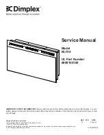
EXPLODED PARTS DIAGRAM
Replacement Parts List
12
6
1
2
3
4
14
10
11
7
13
8
9
1. Element. . . . . . . . . . . . . . . . . . . . . . . . 2200510300RP
2.
Partially Reflective Glass
. . . . . . . . . . 5902700100RP
3.
Blower
. . . . . . . . . . . . . . . . . . . . . . . . . 5300170300RP
4.
Front Glass
. . . . . . . . . . . . . . . . . . . . . 6909140100RP
5. Power Cord . . . . . . . . . . . . . . . . . . . . . 8400320100RP
6.
Flicker Motor
. . . . . . . . . . . . . . . . . . . . 2000220100RP
7.
Flicker Assembly
. . . . . . . . . . . . . . . . 5902720100RP
8. Cutout . . . . . . . . . . . . . . . . . . . . . . . . . 2300201500RP
9. LED Light Panel . . . . . . . . . . . . . . . . . 3000830100RP
10. Remote Receiver . . . . . . . . . . . . . . . . 3000821000RP
11.
Switch Board
. . . . . . . . . . . . . . . . . . . . 3000821100RP
12.
LED Driver Board
. . . . . . . . . . . . . . . . 3000810200RP
13. On/Off Switch . . . . . . . . . . . . . . . . . . . 2800070700RP
14. Remote Control . . . . . . . . . . . . . . . . . . 3000370900RP
15. Glass Media . . . . . . . . . . . . . . . . . . . . 1400070100RP
16.
Mounting Kit
. . . . . . . . . . . . . . . . . . . . 9600770100RP
Accessories
17. Wall Switch Remote Control . . . . . . . . . . .
WRCPF-KIT
OEM Accessory
River Rocks . . . . . . . . . . . . . . . . . . . . . . . . . . . . . .
DFS1314
5


