


8
www
dimplex
F
om
Fireplace Installation
hanging
F
omponents are
designed for use with Dimplex
¿
repla
F
es only
Improper use
or use for purposes other than
intended
may
F
ause damage
or in
M
ury
Wall Hanging Instructions
WARNING:
)
ailure to install
the
¿
repla
F
e as instru
F
ted
below may result in damage
to the equipment and or may
expose the user to the risk of
¿
re
serious in
M
ury
illness or
death
WARNING:
The
¿
repla
F
e
requires the wall hanging
bra
F
ket s
F
rews to be installed
into a minimum of one wall
studs (
)
igure 1)
Tools Required
2 Phillips s
F
rewdriver
Pen
F
il
6
lot s
F
rewdriver
%
ubble level (supplied)
Drill
and drill bits as required
Approximate time:
30 minutes
for installation
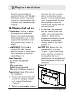
1
Remove the two s
F
rews that
se
F
ure the hanging bra
F
ket
to the ba
F
k of the
¿
rebox
(
)
igure 1)
2
6
ele
F
t an appropriate lo
F
ation
Figure 1
to mount the unit on a wall
above an ele
F
tri
F
al outlet
$FF
ess to the ele
F
tri
F
al outlet
must be maintained
(
nsure
the installation meets the
national and state
provin
F
ial
ele
F
tri
F
al
F
odes
!
NOTE:
It is re
F
ommended
that the bottom of the unit
not be mounted higher than
1020mm (40") from the
)
irepla
F
e Installation ground
to maintain an optimized
viewing angle of the
À
ame
(
)
igure 2)
CAUTION:
(
nsure that the
top of the unit is at least
152mm (6") from the
F
eiling
or any ob
M
e
F
t (i
e
(
le
F
tri
F
al
re
F
epta
F
les) that may
obstru
F
t or be sus
F
eptible the
À
ow or temperature of air out
of the unit


