


8 www.dimplex.com
!
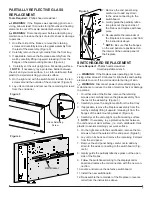
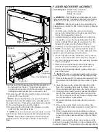
NOTE:
Be sure that the flanges on the end panel are
positioned on the interior of the outside panel of the fire
-
place.
DISPLAY/CONTROL BOARD
REPLACEMENT
Tools Required:
Phillips head screwdriver
WARNING:
If the fireplace was operating prior to ser
-
vicing, allow at least 10 minutes for light bulbs and heating
elements to cool off to avoid accidental burning of skin.
WARNING:
Disconnect power before attempting any
maintenance to reduce the risk of electric shock or damage
to persons.
1.
On either side of the firebox, remove the retaining
screws and carefully remove the glass assembly from
the rest of the assembly. (Figure 3)
2. Carefully remove the acrylic media from the front tray.
3.
If applicable, remove the fireplace assembly from the
wall by carefully lifting it upward, releasing it from the
flanges of the wall-mounting bracket. (Figure 4).
4.
Carefully set the unit upright on a flat working surface.
!
NOTE:
If necessary, lay a protective barrier between
the unit and your work surface, (i.e. cloth, cardboard, thick
plastic) to avoid scratching your work surface.
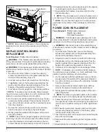
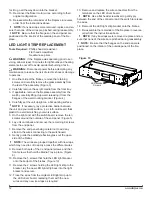
5. On the right end, with the switchboard, remove the ten
screws around the outside of the end panel. (Figure 5)
6. Lay unit on its back and remove the remaining 9 screws
from the end panel.
7. Remove the end panel being careful not to add any
strain to the wires connecting to the switchboard.
8.
Gently guide the partially reflective glass out the open
side of the firebox.
!
NOTE:
The wires are grouped together with tie wraps,
which may need to cut to easily access the different wires.
9. Locate the display/control board and remove the two
screws that secure the assembly to the unit. (Figure 6)
10. Carefully transfer the wire connections from the original
control board onto the new control board.
11.
Re-assemble the fireplace in reverse order from the
instructions above.
!
NOTE:
If any tie wraps were removed, replace and en-
sure that none of the wires are pinched during reassembly.
!
NOTE:
Be sure that the flanges on the end panel are
positioned on the interior of the outside panel of the fire
-
place.
POWER CORD REPLACEMENT
Tools Required:
Phillips head screwdriver
Needle-nose pliers
Flat Head Screwdriver
WARNING:
If the fireplace was operating prior to ser
-
vicing, allow at least 10 minutes for light bulbs and heating
elements to cool off to avoid accidental burning of skin.
WARNING:
Disconnect power before attempting any
maintenance to reduce the risk of electric shock or damage
to persons.
1.
On either side of the firebox, remove the retaining
screws and carefully remove the glass assembly from
the rest of the assembly. (Figure 3)
2. Carefully remove the acrylic media from the front tray.
3.
If applicable, remove the fireplace assembly from the
wall by carefully lifting it upward, releasing it from the
flanges of the wall-mounting bracket. (Figure 4).
4.
Carefully set the unit upright on a flat working surface.
!
NOTE:
If necessary, lay a protective barrier between
the unit and your work surface, (i.e. cloth, cardboard, thick
plastic) to avoid scratching your work surface.
5. On the right end, with the switchboard, remove the ten
screws around the outside of the end panel. (Figure 5)
6. Lay unit on its back and remove the remaining 9 screws
from the end panel.
7. Remove the end panel being careful not to add any
strain to the wires connecting to the switchboard.
8.
Gently guide the partially reflective glass out the open
side of the firebox.
!
NOTE:
The wires are grouped together with tie wraps,
which may need to cut to easily access the different wires.
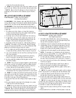
9.
Follow the wiring from the power cord (Figure 6) up to
the upper cavity of the unit, removing any tie wraps and
remove the connections, taking note of the original loca-
tions.
10. With needle nosed pliers, squeeze and push the grom-
met securing the power cord out of the casing, going
into the upper cavity of the unit.
11. Insert the new power cord and grommet, reattaching the
wire with new tie wraps.
12.
Reconnect the wires according to their original configu
-
ration.
13.
Re-assemble the remainder of the fireplace in reverse
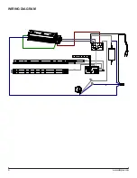
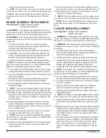
Figure 6
Heater Assembly
AC/DC Adapter
Relay Board
Display/Control
Board
Switch
Board
Power
Cord


