6 www.dimplex.com
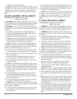
WIRING DIAGRAM
CN3
CN4
CN6
Страница 1: ...rth America Limited Dimplex North America Limited 1367 Industrial Road Cambridge ON Canada N3H 4W3 1 888 346 7539 www dimplex com REV PCN DATE 00 13 JAN 16 01 3 MAY 16 IMPORTANT SAFETY INFORMATION Alw...
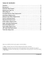
Страница 2: ...not carefully followed will expose the user to the risk of fire serious injury or death Operation 3 Maintenance 4 Exploded Parts Diagram 5 Replacement Parts List 5 Wiring Diagram 6 Partially Reflectiv...
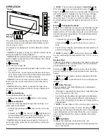
Страница 3: ...heme of the cycle is a prism where the unit cycles through a variety of colors Pressing the button stops the cycling and holds the unit on the preferred color indicated by a solid circle When the unit...
Страница 4: ...w H high and L low H Sleep Timer The Sleep Timer can be set to automatically shut off the fireplace after a preset time from 30 minutes to 8 hours To set the timer press the timer button on the remote...
Страница 5: ...rdware Kit 9600350100RP 8 Mounting Bracket 1017130259RP 9 Display Control Board 3001430200RP 10 Switchboard 3001520100RP 11 Relay Board 3001440200RP 12 AC DC Adapter 2100250100RP 13 Remote Control 670...
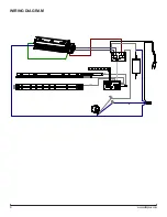
Страница 6: ...6 www dimplex com WIRING DIAGRAM CN3 CN3 CN4 CN6 CN6 CN4...
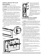
Страница 7: ...remaining 9 screws from the end panel 7 Remove the end panel being careful not to add any strain to the wires connecting to the switchboard Fig ure 6 8 Gently guide the partially reflective glass out...
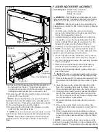
Страница 8: ...the flanges on the end panel are positioned on the interior of the outside panel of the fire place POWER CORD REPLACEMENT Tools Required Phillips head screwdriver Needle nose pliers Flat Head Screwdr...
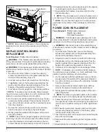
Страница 9: ...ront panel the 3 screws along the back of the unit Figure 7 and the 5 screws on the left hand panel 11 Reconnect the wires according to their original configu ration 12 Re assemble the remainder of th...
Страница 10: ...r cavity and remove all of the wiring connections noting their original location 13 Connect the wiring to the new heater assembly and re place the four screws to secure the assembly to the unit 14 Re...
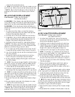
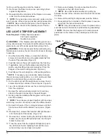
Страница 11: ...t on a flat working surface NOTE If necessary lay a protective barrier between the unit and your work surface i e cloth cardboard thick plastic to avoid scratching your work surface 5 On the right end...
Страница 12: ...d scratching your work surface 5 On the right end with the switchboard remove the ten screws around the outside of the end panel Figure 5 6 Lay unit on its back and remove the remaining 9 screws from...
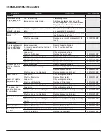
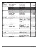
Страница 13: ...er adapter 2100250100RP Fireplace does not turn on in Remote Mode Improper operation Refer to Operation Section Remote Control not working Install new battery into the Remote Control Replace Remote Co...
Страница 14: ...ly Replace Heater Assembly 2203610400RP Heater emits an odor Normal Operation Normal operation is when the heater emits an odor for a brief period after the heater is initially turned on The heater is...