


26
INSTALLATION OF THE INFRARED
SURVEY SYSTEM
(Photocells).
This operation shall be carried out according to the
manufacturer’s instructions only. According to the per-
fect assembly position, the optical axis between the
receiver and the infrared transmitter should be 30-60
cm from the ear th and 10 cm from the door.
External side
Internal side
Operation: during the gate closing, when passing
through the photocells, the gate stops and opens
again, to avoid the obstacle.
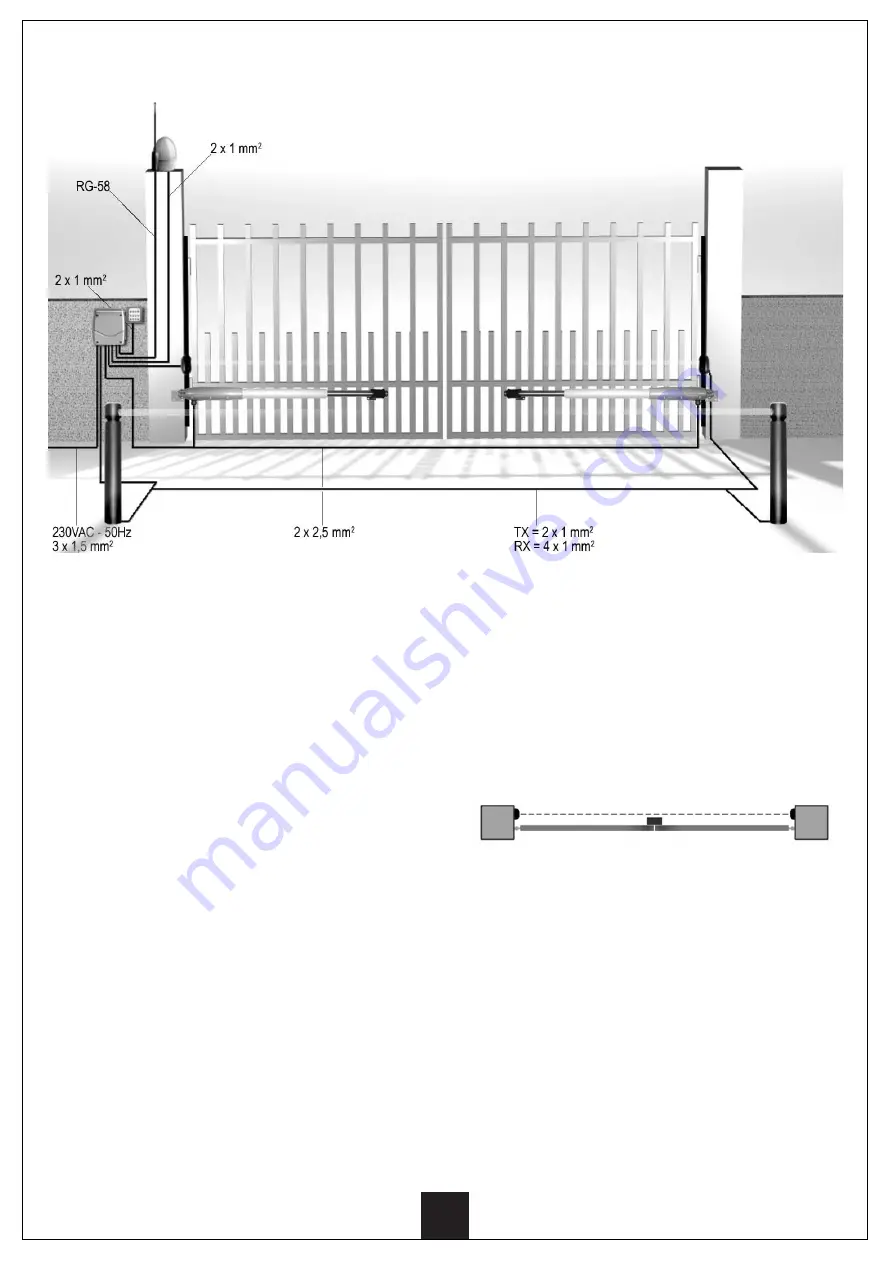
INSTALLATION LAYOUT
INSTALLATION OF THE CONTROL
BOARD
The control board should be installed next to the gate,
to avoid too much long connecting wiring.
Make use of dowels which are suitable to the kind of
wall (for instance: brick or cement).
INSTALLATION OF BLINKING LAMP
AND CONTROL DEVICES
(safety and control buttons).
The blinking lamp shall be installed in the most visible
position both inside and outside the gate.
The control button can have series or parallel connec-
tions (by properly programming the power plant accor-
ding to the indications shown in table 2).
The series connection is mandator y for the safety block
buttons.
EXTERNAL ANTENNA
It deals with a wide range antenna having a 433.92
MHz frequency, equipped with a fastening device and a
2,5 m RG – 58 coaxial cable.
NOTE
: We recommend using external antenna model
ANS433
in order to ensure the largest radio range.
Содержание KIT BATT12V
Страница 2: ...KIT BATT12V INSTRUCCIONES 1 INSTRU ES 11 INSTRUCTIONS 21 NOTICES 31 ANLEITUNGEN 41 E P GB F D...
Страница 53: ......
Страница 54: ......


