background image

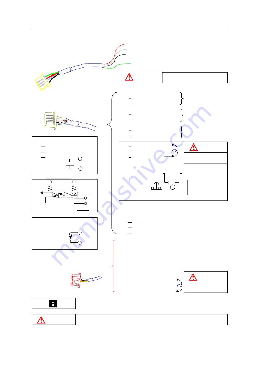
❖Wiring

Red

R(200V 50/60Hz)

PC-A

Power cable

White

S(200V 50/60Hz)

0.75mm

2

Black

T(200V 50/60Hz)
Not wiring when single phase

Green/Yellow

E(Earth)

1

PC-B

Signal cable

2

0.5mm

2

Option

3
4

5
6

Wire #

1:2

1A at AC 250V or less

7

3:4

1A at DC 30V  or less

5:6

8

24V GND

Example for circuit

7           8

Wire # 7:8  9:10  11:12

S5:S6

  0V   EMG

100V

5V

24V

CPU

7,9,11 ,S5

5V GND

8,10,12, S6

9

Feed input

Wire #

1A at AC 250V or less

10

24V GND

S1:S2

1A at DC 30V or less

11

Release input

S3:S4

12

24V GND

S1
S2
S3

PC-C

S4

0.5mm

2

Option

S5

S6

Blown:24V GND

Need to short, if not
using.

Black:Emergency stop

DANGER

To cover each cable which is not using connection.

CAUTION

Yellow:Press cont.
processing

Need to short, if not
using.

Need to short the circuit of press processing select(S5, S6), if you don't use the
circuit.

To the stop continuous
on the press circuit

Work shortage sensor
output

To the stop continuous
on the press circuit

Continuous stop signal
output

To the stop continuous
on the press circuit

Red:Emergency stop

To Emergency stop circuit

Input stop
of Feeder

Press cam signal

CAUTION

You can select which 3 phase or single phase. If it's single phase, you don't have to connect the black wire.

Press cam signal

White:Emergency stop

To Emergency stop circuit

DANGER

Connect to the primary side

Emergency and press
processing select

Green:Emergency stop

Drive stop signal output

3

Содержание J06

Страница 1: ...nc Feed Release Usually the Release mode does not display Press the both switches of Sync Feed and Sync Release switches then the controller will be able to receive the sync press cam signals Signal Feed Release Scale for pass line on the bracket 1 TS8 03 2 NTS8 02 Only when changing settings item the Release mode is supposed to display on the Feed Length after displaying digit of lowest of Feed L...

Страница 2: ...nting position Top view Mounting position 2 6 3 7 4 8 5 9 1 not use a h for J15 h g f e d c b a J06 70 Balance of confirmation Assembly drawing of the bracket 88 138 100 h Bolster 153 203 173 223 58 108 128 178 63 113 48 98 78 128 Bolster 9 8 7 6 5 4 3 2 1 h 75 h 100 178 228 108 158 73 123 98 148 133 183 158 208 h 0 h 25 h 50 113 163 188 238 138 188 123 173 148 198 h 125 33 83 203 253 163 213 CAUT...

Страница 3: ...GER To cover each cable which is not using connection CAUTION Yellow Press cont processing Need to short if not using Need to short the circuit of press processing select S5 S6 if you don t use the circuit To the stop continuous on the press circuit Work shortage sensor output To the stop continuous on the press circuit Continuous stop signal output To the stop continuous on the press circuit Red ...

Страница 4: ...side the connecting cover Connecting cover Air piping TS8 03 NTS8 02 To solenoid valve Approximate air pressure 0 3 0 5 MPa Maximum air pressure 0 5 MPa NTS8 02 Air passes in specific direction CAUTION DANGER Need to fix three external cables in prepared nylon band 4 ...

Страница 5: ...he press cam signal Release timer setting It can be input from 0 001sec to 0 05 sec Input time period the release carry out Input the release strat using the press cam signal The delay time will vary depending in the springs pressure NOTE Need to set the ON of the feed signal to the feed completed angles when using option Overrun Function Set the ON to the release start angle and set the OFF to th...

Страница 6: ...nsor Setting mistake Motor connection anomaly Initial setting mistake Contact failure Number State Content Note Setting mistake of the motor capacity J06 After releasing the Emergency stop switch turn off the power Model number ENG STOP Turn on Sync Feed and Sync Release after turn on Reset switch Turning off Sync Feed the work shortage sensor will disabled I F 7 7 7 7 7 7 666666 Contents CC When ...

Отзывы: