


18
Place a bullet on the belled case
mouth and lower the toolhead. Then,
raise the toolhead just enough to inspect
the bullet without indexing the
shellplate. If the bullet is not seated deep
enough, screw the seating die down 1/2
turn at a time. As a guide, one full turn
moves the die down about 70 thou-
sandths of an inch, about the thickness of
a nickel. Again, cycle the machine and
inspect the seating depth. Repeat these
steps as necessary until the correct over-
all length is achieved. Use a dial caliper
or equivalent to measure the overall
length of the cartridge. Check the overall
length of the round against the informa-
tion in your reloading manual.
Once you have obtained the proper
OAL, replace the cartridge into Station 7
and lower the toolhead. Using a 1"
wrench to turn the lock ring and a 7/8"
wrench to hold the die body, snug the
lock ring.
Note: If you ever load a cartridge that
you are unhappy with, you can use a
Dillon bullet puller to reclaim your com-
ponents.
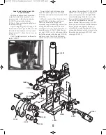
Station 8 - Installation and adjustment
of the Crimp Die
Screw the crimp die into Station 8.
Screw it down until it is flush with the
bottom of the toolhead. This is a good
starting point for the crimp adjustment.
Place a cartridge with a properly
seated bullet into Station 8.
Lower the toolhead and continue to
screw the die down until it touches the
cartridge.
Fig. 58
Raise the toolhead and screw the die
down 1/8 of a turn, lower the toolhead.
Raise the toolhead halfway and in-
spect the cartridge. If the bell is still pres-
ent, or the desired amount of crimp has
not been achieved, give the die a 1/8
turn down and try again. Continue mak-
ing small adjustments to your crimp die
until the desired amount of crimp has
been achieved.
Once the adjustment is complete,
place the case back into Station 8 and
lower the toolhead. Using a 1" wrench
to turn the lock ring and a 7/8" wrench
to hold the die body, snug the lock
ring.
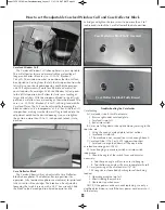
Note: When adjusting the crimp die it
is important to know what to look for.
Check that the crimp: Looks OK, allows
your firearm to function consistently and
the bullet feels tight in the case.
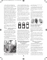
The drawing of case #3 (above) is a
depiction of a case that has been over
crimped by adjusting the crimp die down
(clockwise) too far. Note the defined line
below the mouth of the case and the
bulge below the line. This is not a proper
crimp. This line is the direct result of the
cartridge being over crimped. A line like
this will only appear if the crimp die is
adjusted down too far. Warning: Over
crimping .45ACP, .38 Super, 9mm,
etc., can actually cause the bullet to
be loose in the case.
Adjustments for calibers 9mm, .38 Sp.,
.45 ACP and for hot loads that have
been fired many times
Configuration 1
To begin, place a military case (sized,
decapped and unswaged) into Station 3.
Screw the back-up rod (#12749*)
down two turns into the toolhead
(#20420). Pull the handle.
Using a wrench turn the back-up rod
(#12749*) down until it hits the inside
bottom of the case. Note: Do not force
the expander as this will damage the
case and the shellplate. Now secure the
lock ring (#14062). Raise the handle.
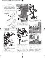
Screw the eyebolt (#13245) all the
way into the swager. Grease the clevis
pin (#13522) heavily.
Put the swager into position. Push the
clevis pin through the connecting rod
and eyebolt and secure with the hitch
pin (#13840). Replace the swage cover
(#13064).
With the military case still in Station
3, pull the operating handle down with
your left hand. Now turn the swager
upward with your right hand until it
meets resistance. With your left hand
raise the operating handle about 10
inches. With your right hand turn the
swager up a 1/4 turn. Cycle the handle
down.
Raise the handle just enough to re-
move the case and inspect the primer
pocket to see the amount of swaging
being done. The swager should leave a
radiused entrance on the primer pocket.
Fig. 59
Turn the swager in, using 1/4 turn in-
crements until you achieve the proper
swage. Secure the jam nut (#13682).
Note: Do not over swage. This condi-
tion will cause damage to the shellplate
(#12600*).
When your swager is properly ad-
justed you will feel resistance during the
final 1/2" to 1" of the downward stroke of
the handle.
Adjustments for rifle calibers
Configuration 2
To begin, place a military case (sized,
decapped and unswaged) into Station 3.
Remove the back-up rod (#12749*)
from the back-up die (#12184).
With the operating handle in the down
position, screw the back-up die into Sta-
tion 3 until the die comes into contact
with the shellplate. Now back the die out
one full turn and secure it in place with
the lock ring (#14067).
Leave the handle in the down posi-
tion. With a wrench, screw the back-up
rod into the back-up die. Turn the back-
up rod down until it touches the inside
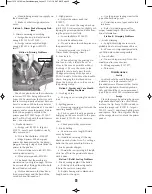
Fig. 58 - Cutaway crimp die shows the
area being crimped while the case is being
fully supported by the die body.
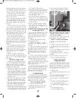
Fig. 59 - Note the difference between the
swaged primer pocket (left) and the
unswaged primer pocket (right).
3
2
1
Super 1050 2018 New Casefeeder.qxp_Layout 1 1/31/18 6:47 AM Page 18