background image

Digitronic

Digital Cam Switch Unit

Automationsanlagen GmbH

CamCon DC16

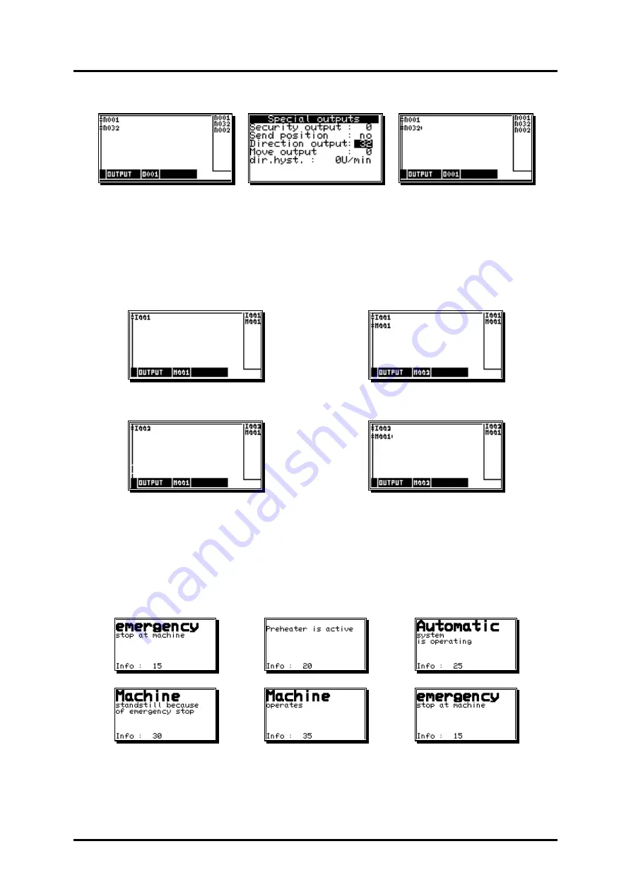
Example 2:

Output depending on the rotation direction.

Output 1 of the CamCon is

Output 1 of the CamCon is

enabled when the rotation

enabled when the rotation

direction output 32

direction output 32

is 

active

.

is not 

active

.

This is the case when the direction

This is the case when the direction

of the rotation is 

positive

.

of the rotation is 

negative

.

Example 3:

Flank assessment.

Register 2 is activated for one cycle when the signal at input 1 changes from 0 to 1.

Register 2 is activated for one cycle when the signal at input 2 changes from 1 to 0.

7.5.3.2.2. PLC Logic Module with text display

Available with the PLC Logic Module is a text display you can use to show and describe the different
states of your machine.

Example:

Version: Aug. 04

Page: 70

Содержание CamCon DC16

Страница 1: ...Digitronic Automationsanlagen GmbH Steinbeisstra e 3 D 72636 Frickenhausen Tel 49 7022 40590 0 Fax 10 Auf der Langwies 1 D 65510 H nstetten Wallbach Tel 49 6126 9453 0 Fax 42 Internet http www digitr...

Страница 2: ...mentioned limits to liability do not apply to insurance of named characteristics and damages which were caused deliberately or through negligence Protection The CamCon DC16 and this instruction manua...

Страница 3: ...7 1 1 Closedown resistors with DIP switch 17 4 1 7 1 2 Closedown resistors with solding bridges 18 4 1 8 Clamping allocation of a serial RS232 interface optional 18 4 2 External interface option 19 4...

Страница 4: ...e actual position hysteresis 44 7 4 1 3 Controlling the measuring system 45 7 4 1 4 The electronic gear 46 7 4 1 4 1 Electronically changing the rotation direction 46 7 4 1 5 The display format of the...

Страница 5: ...6 7 5 1 3 Checking the key configuration 66 7 5 2 Complete deletion 67 7 5 3 Unit configuration 68 7 5 3 1 Setting the serial interface 68 7 5 3 1 1 The Cam BUS communication mode 68 7 5 3 1 2 The Sta...

Страница 6: ...full 79 9 8 Problem The EEProm memory is full 80 9 9 Problem Outputs will not activate 80 9 10 Problem Out Error 80 9 11 Problem Error in the EEPROM 80 9 12 Problem Error 80 9 13 Problem Clear 81 10...

Страница 7: ...ch components for switch ON and switch OFF points can be set in steps of 100 s separately DTC delay time or Speed Compensation Position Triggert Time Cams Power supply 24V DC 20 Mounting of suspension...

Страница 8: ...e presented as three tracks occur when the three cam disks turn anti clockwise past a sensor which scans the cams on the 0 axis In a mechanical cam switch unit the switch interval i e the range betwee...

Страница 9: ...zzle opens for a short time during which a drop of glue ejects Between the start of the impulse and the exit of the drop time passes which is mainly caused by the delay time of the magnetic valve TMV...

Страница 10: ...on by the distance x vpaper Ttotal delay 1m s 30ms 30mm In order to compensate the delay time the switch point for the magnetic valve must be moved forward by 30 If the speed of the device and consequ...

Страница 11: ...is calculated at a speed of for example 50 rpm We assume that the programmed switch point lies at 200 in this case The second measurement is taken at a speed of 80 rpm The necessary switch point must...

Страница 12: ...2 Now calculate the delay time taking into account the distance and speed difference using this formula Delay time in sec way in 60 sec min Speed in rpm 360 turn 340 332 60 40 30 360 0 133 sec The cal...

Страница 13: ...ntering delay time see Chapter 7 3 3 Programming the delay time on page 32 Attention If the switch off point of a Cam overtakes the switch on point at rising speed the result will be an non defined si...

Страница 14: ...ered and the cover has to be grounded on both ends The connection cable for the measuring system or the serial interface also has to be covered and the cover has to be grounded on both ends Analog sig...

Страница 15: ...measuring system encoder Pin 12 A impulse Pin 13 B impulse Pin 14 Clear 1 Pin 15 Clear 2 Pin 16 24V DC voltage supply of the incremental measuring system encoder 4 1 4 Pin allocation of the outputs 1...

Страница 16: ...onfiguration on page68 is necessary Interface converter with bridged closedown resistors CamCon DC16 Unit number 0 with bridged closedown resistors CamCon DC16 Unit number 0 with bridged closedown res...

Страница 17: ...r end of a linked chain or single device as well as at the interface converter Pin 1 with Pin 2 and Pin 3 with Pin 4 A new CamCon comes with these soldering bridges closed so that they have to be open...

Страница 18: ...cuit board If these are closed the RS485 conduction is closed with a resistance of 390 150 390 Ohm Both bridges have to be either both open or both closed since an asymmetrical charge disturbs the dat...

Страница 19: ...CamCon DC16 is plugged into the 10 pol plug ext Int IN at the CamCon module The cable is included in your order of the extension modules The data transfer is made free of potential with an optical co...

Страница 20: ...measuring system and can be set in the CamCon Note The data record corresponds to the Stegmann SSI Standard Clock Data Tp clock impulse max 1MHz to min 66kHz adjustable through the cable length Tmono...

Страница 21: ...r to stop synchronisation zero setting of the counter a further clear signal Clear 2 is available on the CamCon The signals Clear 1 and Clear 2 are to standard AND linked and can be changed in their f...

Страница 22: ...r SINCOS CamCon Since the absolute measuring system of the Hiperface interface is not used and no clear signals are available the CamCon must be initialized after each restart This must be done by the...

Страница 23: ...as a measuring system Systems which are controlled by elapsed time In this case the CamCon makes a time available with a time basis of minimum 1 ms as actual value Through laying on of input signals i...

Страница 24: ...nputs of the CamCon have not been covered with functions by the factory The user would have to do this himself in the process of setting system data of the CamCon depending on his requirements See cha...

Страница 25: ...ter selection during text input or PC PageUp key choose cam deactivation point character selection during text input or PC PageDown key input of cams special measuring systems character during text in...

Страница 26: ...in the new position of the cursor simplifying making repeated inputs of the same character If you have made an error you can go back to the wrong character to correct it using the key or the key This...

Страница 27: ...supply voltage the program memory is not in a defined state So when first using the CamCon unit you have to put a complete deletion into operation as follows 1 Press the key you leave the standard dis...

Страница 28: ...d order of the parameterization You can find the neccessary information in the corresponding chapters 1 System setting System upgrading See chapter 7 4 6 System upgrading on page 62 2 System setting C...

Страница 29: ...m is put into a slow motion the respective actual position is shown on the display With increasing rotation velocity the device switches at a defined point 5 to a display showing the current speed in...

Страница 30: ...il the selection is complete see chapter 7 4 6 8 Setting the program selection mode on page 63 7 2 3 Program name With the CamCon you can assign a text to the stored programs This is recommended when...

Страница 31: ...m The lower part displays an output with programmed cams and their activation and their deactivation points If no input is made within two minutes the CamCon automatically returns to the main menu for...

Страница 32: ...delay time you want to compensate With the numeric keys you can enter the delay time that you need to compesate By pressing the key while entering the effects of the speed compensation for the switch...

Страница 33: ...Press while entering followed by pressing to switch on your way Cam so that you are able to enter the switching time in steps of 0 1 ms Pressing while entering the switching time will switch of the C...

Страница 34: ...is underlayed in black while a stylized cam blinks in the range of the two bars With the numeric keys you enter the position for the cam activation point After you confirm your selection with the key...

Страница 35: ...vation or deactivation point during cam programming you can assume the current actual position for the field by pressing the key The actual position is displayed and brought up to date until the or ke...

Страница 36: ...cursor to yes with the key and press the key to confirm your choice 7 3 11 Output cam track deletion If you want to completely erase an output cam track you have to press the key to enter the input of...

Страница 37: ...the cursor to yes with the key and press the key to confirm your input This starts the copying process After a short while the new output will appear on the display 7 3 13 Shifting cam tracks With the...

Страница 38: ...ms This is done as follows 1 Press the key the cursor moves to the input of the output number 2 Press the key the cursor moves to the input of the program number 3 Select the program you want to copy...

Страница 39: ...ey and enter 4 4 Press the key the cursor moves to the field for speed compensation 5 Enter the value 1000 with the numeric keys 6 Press the key to enter the cam activation point The cursor moves to t...

Страница 40: ...tivation point for an additional cam The cursor moves to the input field for the cam activation point a stylized cam starts to blink simultaneously 5 Enter the value 300 for the cam activation point b...

Страница 41: ...cam programming in the main menu 2 Enter your user code and press the key The programming menu is displayed 3 Select output 4 with the key or press enter 4 and press the key again 4 Select the inserte...

Страница 42: ...log cam starts at the output 33 The output number of the analog cam changes automatically when you change the number of normal outputs see chapter 7 4 6 2 Setting the outputs on page 62 The programmin...

Страница 43: ...on a cam track the programmed analog value is emitted for the whole way of the measuring system 7 3 17 2 Adding an analog cam To add another definition point choose a desired output press the key and...

Страница 44: ...uous Otherwise the CamCon can be adjusted to the measuring system with the and keys You can choose between the following predefined resolutions that are all in accordance with common rotation encoders...

Страница 45: ...te The resolution needs to be a physical measure e g if for a measuring system 4096 Impulses are calculated to 3600 by a 3600 4096 gear the resolution must be set to 4096 Example Cycle time 0 5ms reso...

Страница 46: ...he position is to be shown is mm rather than in angular lines you have reset the gear with the factor 1000 360 The display will no longer change in single steps since the resolution remains unaffected...

Страница 47: ...measuring systems and their settings 7 4 1 6 1 SSI measuring system If you selected SSI for your special measuring system in the measuring system input the following menu is created 1 Enter the bit n...

Страница 48: ...e following scalers can be entered 4 2 1 2 4 8 16 32 64 128 256 512 Here the prescaler is set to 4 This means that a measuring system with a resolution of 500 impulses supplies the device with 2000 im...

Страница 49: ...Enter the total resolution needed Here 360 impulses 360 degrees 2 Enter the total number of rotations Here 3 turns 3 Enter the divisor for uneven translation rates Here 1 4 Press the key to confirm y...

Страница 50: ...nchronous state If you do not want such an output just enter a 0 in this line This output becomes active after the PLL measuring system has been in the synchronous mode for 16 cycles Press the key to...

Страница 51: ...Press the key to confirm your inputs and exit this menu Attention This measuring system may only be used on a CamCon DC50 51 since it blocks the serial interface making the programming via a PC or a...

Страница 52: ...d speed of 120 revolutions per minute is set 7 4 1 6 10 HIPER i e incremental measuring system with Roll Over funktion Having selected HIPER in the measuring system menu the following menbu appears Th...

Страница 53: ...s follows 1 Select the menu point Measuring system in the configuration menu The following menu is displayed 2 Select the special measuring system with the and keys 3 Press the key and the following q...

Страница 54: ...nu point Start you enter the desired begin of the proceeding range You even have the possibility to enter negative values The End value of the measuring range changes automatically and determines the...

Страница 55: ...reset value is copied into the RAM memory of the device This means that after switching the device off and on again the shifting of the actual position equals the zero offset or the offset is no longe...

Страница 56: ...d by inputs in an electronic gear Also see chapter 7 4 1 4 The electronic gear on page 46 7 4 3 2 The display format of the speed display When you have adjusted the speed range with the factor you can...

Страница 57: ...he automatic switching at the 5 of the maximum speed in the Display menu point you can select one of the three different display types with the key and the key Automatic At the 5 point the display is...

Страница 58: ...d This might become necessary if e g you are programming a large number of outputs with delay time or with a high measuring system resolution and need longer single delay times These depend on the ava...

Страница 59: ...in the binary code Exp Output of the actual position in the gray code only for CamCon DC115 Confirm your input with the key 7 4 5 3 Direction output To be able to recognize the direction of the movem...

Страница 60: ...ration of the analog cams With a CamCon cam controller you have the possibillity to make an output of free programmable analog values cams dependent on the position You enter the number of analog outp...

Страница 61: ...ecalculated if necessary The output of the analog value can be stopped by setting an input to a specific value For this purpose enter the input number in the menu point Dis inp Disable Input with whic...

Страница 62: ...of bits see chapter 7 4 5 2 The output of the actual position on page 59 7 4 6 3 Setting the outputs with speed compensation Here you can enter the number of outputs with speed compensation available...

Страница 63: ...re you have the possibility to determine the desired way to change the programs with keys and You can select between slow Here the selected program is built up cam after cam This type of program chang...

Страница 64: ...on YES or off NO by pressing and The keys and are used to select the favoured Outputmuber or Camtrack Pressing quits the input Example Having adjusted the masterprogramnumber 32767 on and switched out...

Страница 65: ...supervisor number You can aquire this number with a phonecall to Digitronic Automationsanlagen 7 5 1 1 Creating a new user key Follow these steps to create a new user key 1 Select the menu point Key a...

Страница 66: ...menu fields for the single access rights with keys and 7 5 1 2 Deletion of a user key You can delete a user key according to the following procedure 1 Select the menu point Key allocation in the conf...

Страница 67: ...nfirm it with After a short while the display returns to the main menu This time depends on the size of the EEPROM used since the memory has to be formatted Using e g a 32k EEPROM the process takes ab...

Страница 68: ...you want the CamCon the daughter display CD10 and the PC via the RS485 BUS Attention Using the configuration above or similar requires that all CamCon devices as well as any connected PC be equipped...

Страница 69: ...ions are described in an extra handbook H PLC which is not in the supply package of the CamCon 7 5 3 2 1 PLC Logic Module The firm Digitronic Automationsanlagen GmbH is an accomplished and well known...

Страница 70: ...when the direction This is the case when the direction of the rotation is positive of the rotation is negative Example 3 Flank assessment Register 2 is activated for one cycle when the signal at inpu...

Страница 71: ...ote With units of increment DC51 S5 DC51 J5 or DC40 S5 this feature is neither necessary nor possible The integrated analog outputs of the CamCon have to be regulated from time to time and after the f...

Страница 72: ...stroyed after a short time If cyclical programming is for a certain reason necessary you therefore have to lock the EEProm Therefore select S EE in menu unit configuration and change it by pressing to...

Страница 73: ...onfigure User in the menu Unit Configuration the following menu appears on your display 7 5 5 1 User text If you selected the menu point User text in the Configuration menu the following menu appears...

Страница 74: ...8 inputs and 24 outputs or using a CamCon 1756 DICAN 0 inputs and 24 outputs 7 5 6 1 CP16 Module If a CP16 Profibus CP16 P or Interbus CP16 I Module gets connected to your CamCon you can switch the CP...

Страница 75: ...exit this menu at all times by pressing the key User text inputs Software version Number of free cams number of programmed cams Maximum delay time setting Maximum setting for the physical resolution o...

Страница 76: ...or the recognition of the stand still speed Analog speed output yes no Number of analog cam outputs Number of inputs and outputs Number of outputs w speed compensation Input number for keyboard lockin...

Страница 77: ...3 analog cam are possible Adjustements for OP functions For each line of a menu page information menus are shown 8 1 Stack Info If a non defined error happens while the CamCon is in operation the user...

Страница 78: ...configuration of the serial interface See chapter 4 1 7 Pin allocation of the serial RS485 interface on page 16 and chapter 7 5 3 Unit configuration on page 68 9 2 Problem Pos Err 1 Possible causes Th...

Страница 79: ...asuring system on page 45 Consult the instruction manual of your measuring system If the error is eliminated the error message can be deleted by pressing 9 6 Problem An Pos Error occurs during operati...

Страница 80: ...terface module e g DC91 IO or DC16 IO Solution See chapter 4 4 The outputs on page 24 See chapter 7 4 6 System upgrading on page 62 See chapter 7 5 6 Configure Hardware on page 74 If the error is elim...

Страница 81: ...emental measuring system Solution Set the Clear signal ON or activate an actual value Preset The result is the immediate release of the Cam Switch Unit Note The incremental measuring system is only av...

Страница 82: ...Digitronic Digital Cam Switch Unit Automationsanlagen GmbH CamCon DC16 10 Menu outline Version Aug 04 Page 82...

Страница 83: ...Speed Compensation 12 Number of output names 24 Number of user keys 66 66 when the special measuring system is available 12 when on Pos program selection is set 48 number of set program names 72 numb...

Страница 84: ...f outputs IActual value resolution 2 If program Mode not slow 8 max delay time 4 cycletime EE Prom size Example 1 The camswitch with a resolution of 360 an EE Promstorage of 32kByte 16 outputs a speed...

Страница 85: ...tandard type AAG612 2048 AAG612 4096 AAG612 8192 AAG626 or AAG66107 Measuring system incremental ADG60 24 500 Border frequency of the incremental input about 100kHz Input level of the incremental inpu...

Страница 86: ...Cam programming 31 Cam search 35 Cam track Deletion 36 Cam BUS 68 CE 2 centre pressure 12 Clamping allocation serial RS232 interface 18 Clear 81 Closedown resistors Serial RS485 interface 17 18 Close...

Страница 87: ...ions 14 HIPER measuring system 52 Hiperface 22 Hysteresis 59 Hysteresis Actual position 44 incremental 52 Incremental measuring system Configuration 48 Incremental measuring system input 21 Input of t...

Страница 88: ...allocation Inputs 15 Pin allocation Outputs 1 8 0 5Amp 15 Pin allocation Outputs 9 16 40mA 15 Pin allocation Serial RS485 interface 16 Pin allocation SSI measuring system 15 Pin allocation Voltage sup...

Страница 89: ...d display Accuracy 57 Speed display Display format 56 Speed display Range adjustment 56 Speed factor 56 SSI measuring system 47 SSI measuring system input 20 Stack Info 77 Standard 68 Standstill outpu...

Отзывы: