Quick Start Guide for GPS160USB V1.00
TEL + 44 1179 554474 www.digitalyacht.co.uk
4. Mode Selection
The GPS160USB can be operated in a number of
different modes, designed to satisfy different installation
scenarios and optimise performance with older systems.
By selecting different modes, you can change the baud
rate, the NMEA 0183 sentences transmitted, the
sentence update rate, satellites used for navigation and
•
GPS at 4800 baud for legacy systems
•
TriNav
™ reception at 38400 baud for new plotters
•
“Turbo Mode” at 115K baud for PC race software
Selection of the operating
mode is via four “DIP” switches
inside the unit. Changes to the switches will become
active when the GPS160USB is power cycled (turned
off/on).
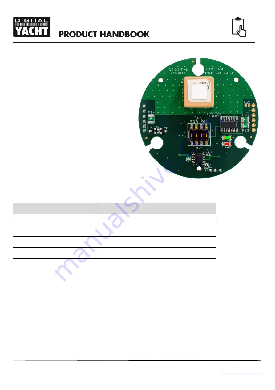
There is a green LED on the PCB that indicates if the
GPS is working correctly and a red LED that illuminates if
there is a fault. The photo of the PCB shows the location
of the LEDs and switches.
Within 2-3 seconds of applying power to the GPS160, the LED should illuminate as follows;
LED State
Description
Green LED ON
Configured correctly for 4800 baud
Green LED Slow Flash
Configured correctly for 38400 baud
Green LED Quick Flash
Configured correctly for 115K baud (Turbo Mode)
Red LED ON
Unused Mode Selected (check DIP switches)
Red LED briefly flashes
A Man Over Board sentence has been transmitted
To access the DIP switches, it is necessary to open the GPS160. It is recommended that this operation is only carried out
by an approved Digital Yacht Dealer/Distributor, any physical damage to the PCB will not be covered by warranty.
Before opening the GPS160, turn off all DC power to the unit and then remove the threaded mount by unscrewing the
3xM3 hex bolts using a suitable Allen Key. Then using a Torx T6 screwdriver, remove the three screws that hold the GPS
enclosure together. Gently pull the enclosure apart being careful not to lose the O-Ring seals (1 large outer and 3 small
screw pillar O-Rings).
Once the GPS160USB PCB is exposed, set the four switches to the relevant positions for the required operating mode as
shown in the table on the next page.
To protect the switches during the surface mount production process, a yellow transparent film is placed
over them. This should be carefully removed using tweezers before attempting to change them.
Содержание TriNav GPS160USB
Страница 1: ...GPS160USB POSITIONING SENSOR...


