background image

-9-

Tilted Table Kit- Assembly Instructions

DigitalTouch Systems

Once everything is connected properly, please test the touch screen to make 

sure everything is fully functional.  Now you’re ready to install the 
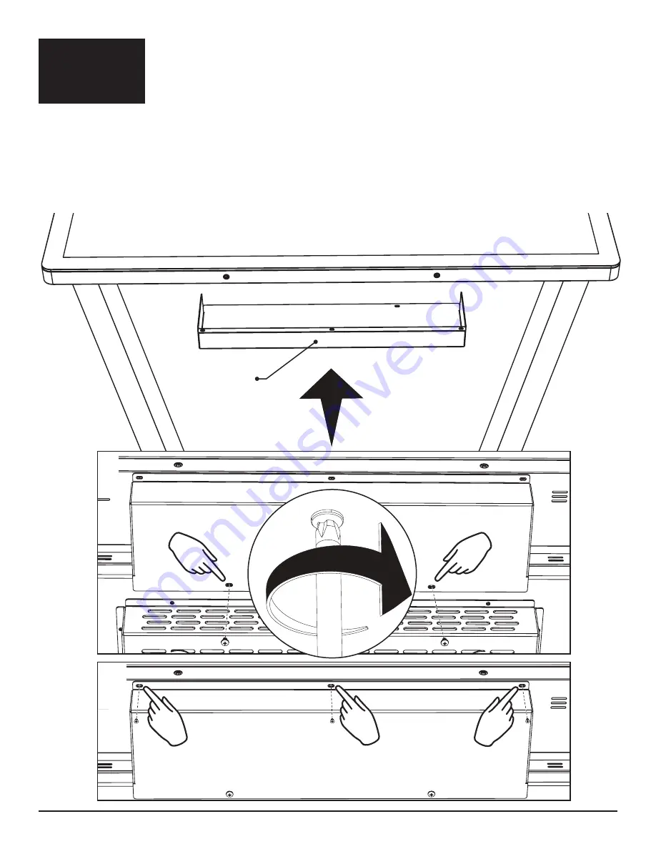
Cover tray

which will cover up any exposed cables after all cable management has been 

done & everything has been tested completely.

Line up the cable 

Cover tray

 with the two holes on the 

Top pan

.

For the three holes on the opposite side of the tray, you will use the three screws on the back of 

the 

Screen

 that line up with these holes.  Please remove these three screws from  the back of the 

screen 

BEFORE

 installing this part.

The side of the tray that is secured to the 

Top pan

 will be installed using the two size 

10-32 x 1/4


inch screws.  Install the two screws on the side that is secured to the 

Top pan

 first, then install the 

three screws on the side of the tray that is secured to the back of the 

Screen

.

Cover tray

1

2

Step 6

Содержание TILTED TABLE KIT

Страница 1: ...Touch Screen Kiosk TILTEDTABLEKIT Assembly instructions...

Страница 2: ...2 Tilted Table Kit Assembly Instructions DigitalTouch Systems Cover tray Parts Screen Top pan Tilt brackets Base Legs...

Страница 3: ...Hardware Included Tools needed 2 Philips Head Screwdriver 20x1 Countersunk Machine Screw x6 20x1 Panhead Machine Screw x8 10 32 x 1 4 Panhead Machine Screw x2 M6x40 Panhead Machine Screw x4...

Страница 4: ...4 Tilted Table Kit Assembly Instructions DigitalTouch Systems Step 1 Attach Base to the Legs using the 6 20 x6 undercut screws provided Baseplate Legs...

Страница 5: ...5 Tilted Table Kit Assembly Instructions DigitalTouch Systems Step 2 Attach the Tilt brackets to the Top pan by using 4 of the 20 panhead screws provided Top pan Tilt bracket Tilt bracket...

Страница 6: ...e PC tray through the center hole and then out through the cutout on the side of the tray as illustrated by the arrows 1 The main power cable will need to be run through the Tilt bracket and into the...

Страница 7: ...all the Top pan to the Screen using the 4 M6 machine screws There are 4 cut outs in the PC tray to allow access for this process Make sure to install the wire cut out of the Top pan in the direction o...

Страница 8: ...uch Systems Step 5 With 2 people attach the Screen Top pan and Tilt assembly to the Legs and Base by resting the assembly onto the Legs and installing the remaining 4 20 pan heads onto either side of...

Страница 9: ...with the two holes on the Top pan For the three holes on the opposite side of the tray you will use the three screws on the back of the Screen that line up with these holes Please remove these three s...

Страница 10: ...support digitaltouchsystems com digitaltouchsystems com 1 512 600 0461...

Отзывы: