2.16 Using Control Representation Mode
The Control Representation Mode is used to print out unprocessed data
or commands sent from the host computer. This procedure is sometimes
referred to as ‘‘dumping.’’ The printing of unprocessed data (in the form
of characters and symbols) is convenient for debugging programs.
If a
specified character is undefined, a hexadecimal representation is printed
in its place.
This section explains how to print the character listing. For additional
information about Control Representation Mode, consult the Digital ANSI-
Compliant Printing Protocol Level 3 Programming Reference Manual.
NOTE:
If the file does not fill the page buffer completely, the remaining
data can be printed by pressing
On Line
to place the printer off line, and then
pressing
Form Feed
to print the partial page.
2.16.1 Entering Control Representation Mode
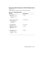
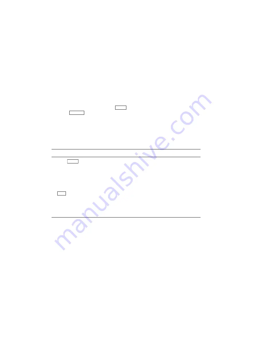
Use the procedure in Table 2–6 to place the printer in the Control
Representation Mode.
Table 2–6: Entering Control Representation Mode
Operation
Display Reads
1. Press
On Line
to place the
printer off line.
— The On Line indicator
shuts off.
00 READY
2. Press and hold
Reset
for about
10 seconds.
03 RESET
#
03 DUMP
#
03 RESET
#
00 READY
DUMP
The printer is now in the Control Representation Mode and ready to accept
data or commands from the printer. To exit the Control Representation
Mode, perform a soft reset (see Section 2.17).
Operating Information
2–51
Содержание DEClaser 2100 plus
Страница 19: ...Figure 1 1 Components Front Right Side View MLO 004826 1 2 Operator s Guide...
Страница 21: ...Figure 1 2 Components Rear Left Side View MLO 004827 1 4 Operator s Guide...
Страница 23: ...Figure 1 3 Components Inside the Printer MLO 004828 1 6 Operator s Guide...
Страница 39: ...5 Replace the cover on the cassette Fig 2 14 MLO 004840 Operating Information 2 13...
Страница 44: ...2 Fold out the extension tray Fig 2 17 MLO 004836 2 18 Operator s Guide...
Страница 48: ...14 Close the rear output tray Fig 2 21 MLO 004834 2 22 Operator s Guide...
Страница 65: ...Figure 2 1 Engine Test Print Fig 2 40 MLO 004525 Operating Information 2 39...
Страница 68: ...Figure 2 2 Test Print A Fig 2 42 MLO 004851 2 42 Operator s Guide...
Страница 72: ...Figure 2 3 Test Print B Fig 2 43 MLO 004852 2 46 Operator s Guide...
Страница 75: ...Figure 2 4 Font List Fig 2 44 MLO 004853 Operating Information 2 49...
Страница 164: ...7 Return the wire pin cleaner to its storage location in the printer Fig 7 22 MLO 004873 Maintenance 7 17...
Страница 182: ...22 Close the top cover by pushing down on the hand grip until it snaps into place Fig 7 46 MLO 004366 Maintenance 7 35...
Страница 224: ...Figure C 2 Serial Connections to Modem MLO 004885 Specifications C 5...
Страница 225: ...Figure C 3 Serial Connections Without Modem MLO 004887 C 6 Operator s Guide...
Страница 228: ...Figure C 4 Parallel Pin Assignment MLO 004886 Figure C 5 Parallel Connections MLO 004888 Specifications C 9...


