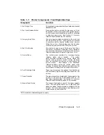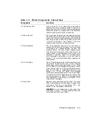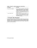
Table 1–2: Printer Components: Rear/Left-Side View
Component
Function
1. Power Switch
Powers the printer on or off.
Pressing ‘‘ | ’’ turns
power on; pressing ‘‘O’’ turns power off. To ensure
that data is not lost, always be sure the display reads
00 READY and the Data indicator is off, before you
power off the printer. See Section 2.1 and Section 2.2
for additional information about powering the printer
on and off.
2. Rear Output Tray
(shown closed)
The rear output tray is selected when you are using
certain types of print media such as transparencies,
labels, and envelopes.
It can also be used when
you want printed output to be stacked faceup.
Refer to Section 2.5 for information about choosing
the different output trays.
See Section 2.5.2 for
information about opening and using the rear output
tray.
3. Memory Board Access Cover
Additional RAM (random-access memory) can be
added to the printer in 1, 2, or 3 MB capacities.
This access cover allows you to easily install the
extra memory board. Refer to the documentation that
comes with the optional memory board for installation
instructions.
4. Parallel (Centronics)
Interface Cable Connector
This connector is used when the interface cable from
the host computer is a parallel cable. Refer to the
DEClaser 2100 plus Printer Installation Guide for
more information about connecting the printer to your
computer.
5. Serial (RS232C)
Interface Cable Connector
This connector is used when the interface cable from
the host computer is a serial cable.
Refer to the
DEClaser 2100 plus Printer Installation Guide for
more information about connecting your computer to
the printer.
6. Power Cord Receptacle
This is where the power cord is connected to the
printer.
Printer Components
1–5
Содержание DEClaser 2100 plus
Страница 19: ...Figure 1 1 Components Front Right Side View MLO 004826 1 2 Operator s Guide...
Страница 21: ...Figure 1 2 Components Rear Left Side View MLO 004827 1 4 Operator s Guide...
Страница 23: ...Figure 1 3 Components Inside the Printer MLO 004828 1 6 Operator s Guide...
Страница 39: ...5 Replace the cover on the cassette Fig 2 14 MLO 004840 Operating Information 2 13...
Страница 44: ...2 Fold out the extension tray Fig 2 17 MLO 004836 2 18 Operator s Guide...
Страница 48: ...14 Close the rear output tray Fig 2 21 MLO 004834 2 22 Operator s Guide...
Страница 65: ...Figure 2 1 Engine Test Print Fig 2 40 MLO 004525 Operating Information 2 39...
Страница 68: ...Figure 2 2 Test Print A Fig 2 42 MLO 004851 2 42 Operator s Guide...
Страница 72: ...Figure 2 3 Test Print B Fig 2 43 MLO 004852 2 46 Operator s Guide...
Страница 75: ...Figure 2 4 Font List Fig 2 44 MLO 004853 Operating Information 2 49...
Страница 164: ...7 Return the wire pin cleaner to its storage location in the printer Fig 7 22 MLO 004873 Maintenance 7 17...
Страница 182: ...22 Close the top cover by pushing down on the hand grip until it snaps into place Fig 7 46 MLO 004366 Maintenance 7 35...
Страница 224: ...Figure C 2 Serial Connections to Modem MLO 004885 Specifications C 5...
Страница 225: ...Figure C 3 Serial Connections Without Modem MLO 004887 C 6 Operator s Guide...
Страница 228: ...Figure C 4 Parallel Pin Assignment MLO 004886 Figure C 5 Parallel Connections MLO 004888 Specifications C 9...


