JTAG-HS2 Reference Manual
Doc: 502-249
page 5 of 5
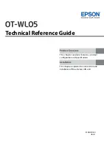
Figure 7
TMS/TDI
TCK
TDO
T
CKL
T
CKH
T
CK
T
CD
T
SU
T
HD
Figure 8
Symbol
Parameter
Min
Max
T
CK
T
CK
period
33.3ns 125µs
T
CKH
, T
CKL
T
CLK
pulse width
16.6ns 62.5µs
T
CD
T
CLK
to TMS, TDI 0
15ns
T
SU
TDO Setup time
19ns
T
HD
TDO Hold time
0
DC Operating Characteristics
Symbol
Parameter
Min
Typ
Max
Unit
VDD (VREF)
I/O reference/supply voltage
1.65
2.5/3.3
5.5
Volts
TDO
Input High Voltage (V
IH
)
1.62
5.5
Volts
Input Low Voltage (V
IL
)
0
0.65
Volts
TMS, TCK, TDI
Output High (V
OH
)
0.85 x Vdd
0.95 x Vdd
Vdd
Volts
Output Low (V
OL
)
0
0.05 x Vdd
0.15 x Vdd
Volts
AC Operating Characteristics
The JTAG-HS2 JTAG signals and SPI
operate according to the timing diagram in
Figure 7. The HS2 supports TCK frequencies
from 30 MHz to 8 KHz at integer divisions of
30MHz from 1 to 3750. Common frequencies
include 30MHz, 15MHz, 10MHz, 7.5MHz, and
6HMz. (See Figure 8)
Copyright Digilent, Inc. All rights reserved. Other product and company names mentioned may be trademarks of their respective owners.