Digilent Cmod S7 Скачать руководство пользователя страница 1

22.8.2018

Cmod S7 Reference Manual [Reference.Digilentinc]

https://reference.digilentinc.com/reference/programmable-logic/cmod-s7/reference-manual

1/12

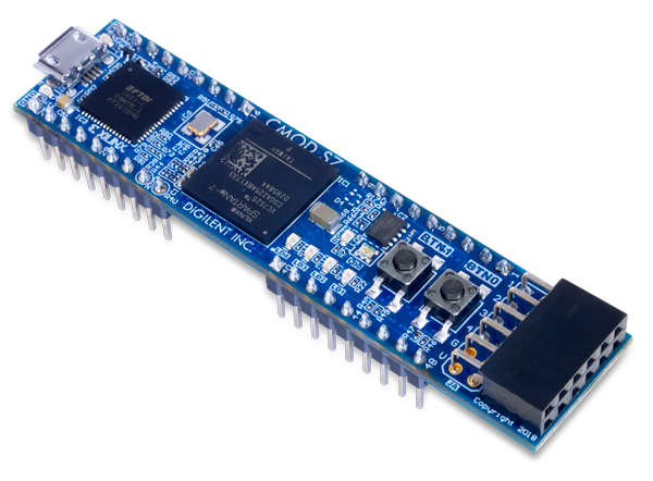
The Digilent Cmod S7 is a small, 48-pin DIP form factor board built around a Xilinx Spartan 7 FPGA. 32 FPGA digital I/O signals, 2
FPGA analog input signals, an external power input rail, and ground are routed to 100-mil-spaced through-hole pins, making the Cmod
S7 well suited for use with solderless breadboards. At just 0.7” by 3.05” inches, it can be loaded in a standard socket and used in
embedded systems. The board also includes a programming ROM (), clock source, USB programming and data transfer circuit, power
supplies, LEDs, and buttons.

(https://reference.digilentinc.com/_media/reference/programmable-logic/cmod-s7/cmod_s7-obl-600.png)

Cmod S7 Reference Manual

Содержание Cmod S7

Страница 1: ...s an external power input rail and ground are routed to 100 mil spaced through hole pins making the Cmod S7 well suited for use with solderless breadboards At just 0 7 by 3 05 inches it can be loaded...

Страница 2: ...22 8 2018 Cmod S7 Reference Manual Reference Digilentinc https reference digilentinc com reference programmable logic cmod s7 reference manual 2 12 Xilinx Spartan 7 FPGA XC7S25 1CSGA225C Features...

Страница 3: ...factor header 32 total FPGA I O 2 single ended 0 3 3V analog inputs to XADC 2 power pins https reference digilentinc com _detail reference programmable logic cmod s7 cmod s7 callout png id reference...

Страница 4: ...e 1 1 The characteristics of the outputs are shown in Table 1 1 https reference digilentinc com _detail reference programmable logic cmod s7 cmod s7 power png id reference 3Aprogrammable logic 3Acmod...

Страница 5: ...to decompress the bitstream itself during configuration Depending on design complexity compression ratios of 10x can be achieved Bitstream compression can be enabled within the Xilinx tools to occur d...

Страница 6: ...l purpose user I O pins after FPGA configuration and can be used like any other FPGA I O https reference digilentinc com _detail reference programmable logic cmod s7 cmod s7 flash png id reference 3Ap...

Страница 7: ...ence manual Figure 5 1 USB UART Bridge The Cmod S7 includes one RGB LED 4 individual LEDs and 2 push buttons as shown in Figure 6 1 The push buttons are connected to the FPGA via series resistors to p...

Страница 8: ...cting to breadboards and custom fixtures The pins have 100 mil spacing and the entire module is 0 7 inches by 3 05 inches Headers J1 and J3 are separated by 700 mil lengthwise along the Cmod measured...

Страница 9: ...r if a user accidentally drives a signal that is supposed to be used as an input The downside to this added protection is that these resistors limit the maximum switching speed of these signals to 25...

Страница 10: ...2 6 pin headers Each 12 pin Pmod connector provides two 3 3V VCC signals pins 6 and 12 two Ground signals pins 5 and 11 and eight logic signals as sown in Figure 8 1 The VCC and Ground pins can deliv...

Страница 11: ...ilentinc com technology partners Distributors https store digilentinc com our distributors Our Partners Technical Support Forum https forum digilentinc com Reference Wiki https reference digilentinc c...

Страница 12: ...ps reference digilentinc com reference programmable logic cmod s7 reference manual 12 12 https instagram com digilentinc https github com digilent https www reddit com r digilent https www linkedin co...

Отзывы: