background image

User Guide 


V 1.8                                                                                                                                                                                    35 / 64 

Access Mode 

The access modes protect the adjustments from erroneous and unauthorized changes. 

Apart from the normal operation mode, the calculator has 2 access modes for the user to work with: 
the User mode the and Service mode. A password is required for both the User- and Service mode. 

In case the calculator is delivered in an officially verified form none of the verification-relevant 
settings can be changed. After 60 minutes without a button-strike the calculator automatically 
changes from the User- or Service-mode to normal operation mode 

The 3

rd

 access mode is the Verification mode for the verification body. This ode can only be 

accessed and left by pressing the verification button. 

In officially verified devices or devices according to the Declaration of Conformity corresponding to 
MID this button is protected by a seal. In case the seal is damaged the verification and Declaration 
of Conformity respectively loses its validity.  

User password: 

100


000


000 

Service password:  200


000


000 

Both passwords can be changed as of Service mode. 


Содержание mwz04

Страница 1: ...V 1 8 1 64 ENERGIE RECHENWERK ENERGY CALCULATOR SCYLAR INT M Type mwz04 Installations und Bedienungsanleitung Installation and User Guide...

Страница 2: ...e 32 Bedienungsanleitung S 34 S 64 Zugriffsebenen 34 Zweikanaliges Energie Rechenwerk 36 Hochaufl sende Anzeigen 36 Sprachauswahl 36 Extremwerte min max Werte 36 Berichte 36 Speicher 38 Alarme 40 Tari...

Страница 3: ...allation of extension modules 33 User Guide P 35 P 64 Access Mode 35 Two channel calculator 37 High resolution displays 37 Language Selection 37 Extremal values 37 Reports 37 Memories 39 Alerts 41 Tar...

Страница 4: ...ichsten vollelektronischen Rechenwerke auf dem Markt In der maximalen Ausf hrung stehen zwei Energiekan le Kanal A und B jeweils mit einem Energiez hler f r W rme und K lte zur Verf gung Das Rechenwer...

Страница 5: ...In the full version there are two energy channels A and B with one energy counter each for heating and cooling available However there are also versions with a reduced number of functions available a...

Страница 6: ...r Programmierung auch Glykol Wasser Gemische Eichrelevante Sicherungszeichen des Rechenwerks d rfen nicht besch digt oder entfernt werden Andernfalls entfallen Garantie und Eichg ltigkeit des Ger tes...

Страница 7: ...cial programming also glycol water mixes Calibration marks on the calculator must not be damaged or removed Their removal invalidates the warranty and calibration of the meter Label seals may only be...

Страница 8: ...g Anschlussklemme geeignet f r bis 2 5 mm galvanische Trennung Leistungsaufnahme max 17 5VA tauschbare Schmelzsicherung 1A tr ge St tzbatterie Bei nicht angeschlossener Netzspannung wird durch eine St...

Страница 9: ...of power supply Terminal suitable for wires up to 2 5 mm2 Galvanic separation Power consumption max 17 5VA Changeable fuse 1A slow blow fuse Back up battery If no mains supply is connected the back u...

Страница 10: ...g of heat t x q x k Leistung Power K ltemessung Measuring of cold t x qx k Leistung Power Forward low temp Return high temp Consumer Verbraucher Energy Calculator K lterechner Cooling System K lte Anl...

Страница 11: ...ower W rmemessung mit Durchflussrichtungs nderung Measuring of heat with a change of flow direction t x q x k Leistung Power or t x q x k Leistung Power high temp low temp Consumer Verbraucher Energy...

Страница 12: ...e eingestellte Impulswertigkeit mit der des jeweiligen Durchflusssensors verglichen werden Vergleiche die Rechenwerkseinstellungen mit den verwendeten Temperaturf hlern PT100 oder PT500 An den Energie...

Страница 13: ...ed with the relevant flow sensors in the same menu Compare the calculator settings with the temperature sensors in use PT100 or PT500 It is possible to connect PT100 or PT500 temperature sensors at th...

Страница 14: ...der Tauchh lse passen Die Tauchh lsen werden am besten im 45 oder 90 Winkel in Einschwei muffen eingebaut Bei der Montage ist darauf zu achten dass das Ende der Tauchh lse sich in der Rohrleitungsmit...

Страница 15: ...cket It is best to mount the sensor pockets in a 45 or 90 angle in a welding sleeve Thereby the tip of the sensor pocket shall be located in the middle of the pipe When mounting the sensor pocked in a...

Страница 16: ...anzuklemmen Falls in dem 10 poligen Stecker Kurzschlussbr cken montiert sind m ssen diese entfernt werden Die beiden roten Dr hte sind an den Klemmen U und I 1 u 5 bzw 3 u 7 anzuklemmen Die beiden we...

Страница 17: ...o be attached to clamps 1 5 6 2 and 3 7 8 4 respectively The short circuit bridges have to be removed in case they are mounted on the 10 pole plug The two red wires are to be connected to clamps U and...

Страница 18: ...peraturf hler Kanal A HIGH TEMP A LOW TEMP A oben schwarz 1 8 u 26 10 Durchflusssensor Kanal A FLOW SENS A mitte schwarz 9 11 u 43 4 Temperaturf hler Kanal B HIGH TEMP B LOW TEMP B oben wei 1 8 u 26 1...

Страница 19: ...rennt galvanisch getrennt max 40 V 100 mA max B rde 500 Ohm Bei 4 Leitermesstechnik Bei 4 Leitermesstechnik die Br cken entfernen die Br cken entfernen verwenden SCHWARZ WEISS HIGH TEMP A LOW TEMP A H...

Страница 20: ...ssel Temperature Sens Cha A HIGH TEMP A LOW TEMP A top black 1 8 u 26 10 Flow Sensor Channel A FLOW SENS A middle black 9 11 u 43 4 Temperature Sens Cha B HIGH TEMP B LOW TEMP B top white 1 8 u 26 10...

Страница 21: ...2 3 3 4 4 230V 50Hz Fuse 230 V 1A Type T 4 Pulse Outputs 40V 1A 4 Analog Outputs 0 4 20 mA galvanic insulation galvanic insulation max 40 V 100 mA max Loadresistance 500 Ohm BLACK WHITE HIGH TEMP A L...

Страница 22: ...erwenden SHARKY FS 473 Impulsausgang und Spannungsversorgung f r SHARKY FS 473 vom Rechenwerk Anschlussklemmen 9 10 und 11verwenden Braun 9 Wei 10 Blau 11 SHARKY FS 475 FUE 380 Impulsausgang Klemmen 5...

Страница 23: ...lamps 10 and 11 SHARKY FS 473 Pulse output and power supply of the SHARKY FS model 473 by calculator Use clamps 9 10 and 11 Brown 9 White 10 Blue 11 SHARKY FS 475 FUE 380 Pulse output clamps 56 57 Use...

Страница 24: ...PT500 Sind die Temperaturf hlerkabel bei den F hlern richtig angeschlossen z B 2 oder 4 Leiter Messung Sind die Temperaturf hlerkabel am Rechenwerk an den richtigen Klemmen angeschlossen Ist der Schir...

Страница 25: ...onnected in the sensors e g 2 terminal or 4 terminal sensing Are the temperature sensor cables correctly connected in the calculator Is the shield of the temperature sensor cables correctly clamped in...

Страница 26: ...ach m glich 1 Das Rechenwerk ffnen und den Anschlussstecker der Spannungsversorgung abstecken Danach die anderen verwendeten Anschlussstecker abstecken Die Schraubklemmen m ssen nicht gel st werden 2...

Страница 27: ...Anschlussplatte des neuen Rechenwerks entfernen und an das alte Rechenwerk anschrauben 5 Das neue Rechenwerk kann nun montiert werden Dazu sind die Befestigungsklammern zuerst in die Oberseite der Sch...

Страница 28: ...can easily be done with just a few simple steps 1 Open the calculator and disconnect the plug of the power supply Then disconnect the other plugs However the screw terminals need not be unscrewed 2 U...

Страница 29: ...l top hat rail 4 Remove the connecting plate of the new calculator and screw it onto the old calculator 5 The new calculator can now be mounted Clip the connecting clips into the upper part of the rai...

Страница 30: ...icht gel st werden 2 Den Flachbandstecker vorsichtig vom Oberteil abziehen 3 Nun wird das Oberteil vom Unterteil getrennt Im weit ge ffnetem Zustand 180 kann man das Scharnier aush ngen Am besten die...

Страница 31: ...nscrewed 2 Carefully disconnect the plug of the ribbon cable from the upper part 3 Now the upper part is separated from the lower part The hinge can be clipped off if the upper part is widely open 180...

Страница 32: ...er Innenseite des Oberteils bei ge ffnetem Rechenwerk links vier Steckpl tze vorhanden 4 Das Modul vorsichtig auf einen freien Steckplatz anstecken und an den vorgesehenen Befestigungen festschrauben...

Страница 33: ...ator has four slots for extension modules They are placed inside the upper part on the left side if the calculator is open 4 The module is to be carefully plugged in an unused plug and screwed to the...

Страница 34: ...vante Einstellungen nicht ver ndert werden Nach 60 Minuten ohne Tastendruck wechselt das Rechenwerk selbst ndig aus der Benutzer oder Serviceebene in den Normalbetrieb F r Eichstellen ist eine 3 Zugri...

Страница 35: ...d After 60 minutes without a button strike the calculator automatically changes from the User or Service mode to normal operation mode The 3rd access mode is the Verification mode for the verification...

Страница 36: ...ew hlt werden Extremwerte min max Werte Es werden die min max Werte mit Datum und Zeit folgender Messgr en erfasst Temperaturen Temperaturdifferenzen Durchfl sse Leistungen Berichte Es gibt Betriebs F...

Страница 37: ...values are saved with date and time in the following measurements Temperature Temperature difference Flow Power Reports There are operating error and alert reports The following can be found in the op...

Страница 38: ...lt der gleiche Startzeitpunkt Mit der Speicher Skalierung wird die zeitliche Einheit festgelegt in der die Werte gespeichert werden min tlich st ndlich t glich monatlich j hrlich Das Speicher Interval...

Страница 39: ...s available All areas have the same starting point The time units minute hour day month year in which the values are saved are selected when using the Memory Scale The Memory interval defines the inte...

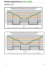
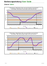
Страница 40: ...t sein damit der Alarm aktiv wird Au erhalb Band muss der Messwert au erhalb der eingestellten Werte des oberen Limit und des unteren Limit sein damit der Alarm aktiv wird Hysterese oben muss der Mess...

Страница 41: ...t of the adjusted value Outside Range in order to activate the alert the measurement value must be outside the upper limit and the lower limit of the adjusted value Hysteresis high in order to activat...

Страница 42: ...imit high30 KLimit low20 K Unteres Limit Limit low Oberes Limit Limit high Temperaturdifferenz Temperature difference Alarm Alert 0 5 10 15 20 25 30 35 40 1 2 3 4 5 6 7 8 9 10 11 12 13 14 15 16 17 18...

Страница 43: ...teresis low Limit high 150 m h Limit low 100 m h Unteres Limit Limit low Oberes Limit Limit high Durchfluss Flow m h Alarm Alert 60 80 100 120 140 160 180 1 2 3 4 5 6 7 8 9 10 11 12 13 14 15 16 17 18...

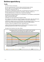
Страница 44: ...edingungen erf llt werden Wenn die 2 Bedingung ausgeschalten ist muss nur die 1 Bedingung erf llt sein damit der Tarifz hler z hlt Zus tzlich zum Z hlwert werden auch die Stunden sowie die H ufigkeit...

Страница 45: ...ndition is switched off only the first condition needs to be fulfilled to start off the tariff counter The hours in which and how often the tariff was active is counted additionally to the count value...

Страница 46: ...ernauslesung der Z hlerdaten m glich Die bertragung erfolgt seriell ber eine verpolungssichere Zweidrahtleitung zwischen den Messger ten Slaves und einem M Bus Pegelwandler Master z B IZAR CENTER Es k...

Страница 47: ...be conducted with the M Bus interface The transmission is serially made via reverse polarity proof two wire line between the external devices slaves and the M BUS level converter master e g IZAR CENT...

Страница 48: ...ombelastung max 100mA Impulsfrequenz max 500 Hz galvanische Trennung JA Opto Mosfet Relais bipolar Pulsweite w hlbar in ms Schritten Pulswertigkeit w hlbar Relaisausgang Relaisausgang Klemmen 50 51 ro...

Страница 49: ...urrent max 100 mA Switching frequency max 500 Hz Galvanic separation YES Opto Mosfet Relay bipolar Pulse length selectable in ms steps Pulse value selectable Relay output Relay output clamps 50 51 red...

Страница 50: ...e Z hlerst nde werden auch im Stichtags und Intervallspeicher abgelegt Durchflusssensor A Klemmen 43 9 10 11 schwarz Durchflusssensor B Klemmen 43 9 10 11 wei Im Men Einstellungen k nnen die n tigen A...

Страница 51: ...se counters are also saved in the due days memory and the interval memory Flow Sensor A clamps 43 9 10 11 black Flow Sensor B clamps 43 9 10 11 white The necessary options for AUX 1 and AUX2 can be se...

Страница 52: ...rgie das Volumen und die Momentanwerte Danach folgt die Hauptauswahl Einige der Anzeigen werden nur in der entsprechenden Zugriffsebene Berechtigung angezeigt Alle wesentlichen Einstellungen sind mit...

Страница 53: ...the momentary values Thereafter follows the main selection Some of the displays are only shown on the relevant access level entitlement All essential settings are adjustable with the four buttons The...

Страница 54: ...Bedienungsanleitung V 1 8 54 64...

Страница 55: ...User Guide V 1 8 55 64...

Страница 56: ...opfzelle die an der oberen Leiterplatte mit einer Haltevorrichtung montiert ist und durch fachkundiges Personal einfach getauscht werden kann muss nicht gel tet werden Achtung Beim Tauschen der Batter...

Страница 57: ...rs It is a button battery that is mounted with a battery holder on the upper PCB It can be simply exchanges by an expert it need not be soldered Attention The verification seal needs to be destroyed w...

Страница 58: ...360m h F r andere Messwerte kann die Pulswertigkeit und Pulsdauer angepasst werden Relais Statussignale 0 60000ms Analogausg nge Messwertzuordnung Ausgangsbereich Limit unten Limit oben Analogausg nge...

Страница 59: ...pulse value and pulse duration can be adjusted for differents measurement values Relay Status Signals 0 60000ms Analog Outputs Value Assigned Output Range Limit Low Limit High Analog Outputs 1 4 Off...

Страница 60: ...falsch angeschlossen T nieder A Fehlerhafte Temperaturmessung beim F hler der an den Klemmen LOW TEMP A Kanal A angeschlossen ist Temperaturbereich au erhalb 50 C 300 C F hlerkurzschluss F hlerbruch...

Страница 61: ...onnected sensors T low A Faulty temperature measuring at the sensor attached to the clamps LOW TEMP A channel A Temperature range beyond 50 C 300 C sensor shorted sensor break wrongly connected sensor...

Страница 62: ...Bedienungsanleitung User Guide V 1 8 62 64 Abmessungen Dimensions 115 mm 240 mm 159 mm...

Страница 63: ...m x 160mm inkl Schrauben und D bel Zur leichteren Montage oder bei Verwendung bestehenden Bohrungen beim Ersatz von alten Rechenwerken Optional accessories Mounting plate 250mm x 160mm incl screws and...

Страница 64: ...tlinie 2006 95 EG MID Richtlinie 2004 22 EG A 0445 3504 2011 Weitere Informationen finden Sie auch unter www ewt at Declaration of conformity for devices according to MID ELIN WASSERWERKSTECHNIK Ges m...

Отзывы: