


Installation Guide
V 1.8 17 / 64
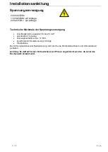
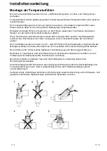
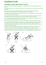
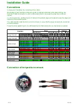
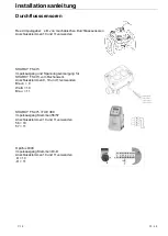
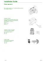
Connection of temperature sensors
Handle the temperature sensors with care!
When connecting the temperature sensors the sensor-cables preferably have to be inserted via the left
bigger cable glands (PG11) and be linked at the connectors 1-5-6-2/ 3-7-8-4 of the 10-pole plug.
See the chart underneath.
The recommended sensor cables can be delivered upon request.
The use of shielded cables for sensors is strongly recommended and the shield is only connected to
the respective clamp 26 on the calculator plug. Sensor cables must not be prolonged.
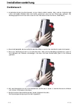
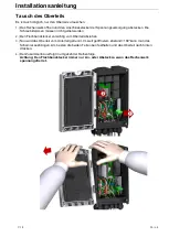
To facilitate the connecting process, the plug has to be removed prior to being clamped to the cables.
The temperature sensors for channel A are to be attached to the black plug and those for channel B
are to be attached to the white plug. (Channel B in case of a 2 channel version)
Temperature sensors have to be paired.
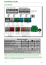
4-terminal sensing
(4T sensing)
Due to metrological reasons 4T sensing is always to be preferred.
In case of bigger or different sensor cable lengths or a small ΔT, 4T sensing is used.
One cable with 4 wires and shield is needed per sensor. The temperature sensors cables have to be
attached to clamps 1-5-6-2 and 3-7-8-4 respectively. The short-circuit bridges have to be removed in
case they are mounted on the 10-pole plug.
The two
red wires
are to be connected to clamps U+ and I+ (1-5 and 3-7 respectively)
The two
white wires
are to be connected to clamps U- and I- (6-2 and 8-4 respectively)
The relevant marking is to be found on the wires.
The clamps for the red wires are marked in red on the connectors of the temperature sensors.
The white wires are connected to the two remaining clamps.
2-terminal sensing
(2T sensing)
When using a 2T sensing (2 wires + shield per sensor) the temperature sensors have to be attached to
clamp 5-6 and 7-8 respectively.
It is necessary to use the 4 short-circuit bridges between the clamps 1-5, 6-2, 3-7, and 8-4.They must
not be removed. The sensor cables have to be of the same type and the same length.
U+
I+
I-
U-
1-
5 6
-2
High Temp.
forward
3-
7 8
-4
Low Temp.
return
1-
5 6
-2
High Temp.
forward
3-
7 8
-4
Low Temp.
return
1-
5 6
-2
High Temp.
return
3-
7 8
-4
Low Temp.
forward
1-
5 6
-2
High Temp
return
3-
7 8
-4
Low Temp
forward
1-
5 6
-2
High Temp.
forward
3-
7 8
-4
Low Temp.
return
1-
5 6
-2
High Temp
forward
3-
7 8
-4
Low Temp
return
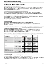
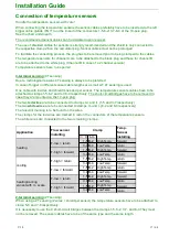
heating/cooling
variant with +/- scale
T-low = return
T-high = forward
cooling
T-high = return
T-low = forward
heating
T-low = return
T-high = forward
Application
Flow sensor
installing
Temp.
Sensor
installing
Clamp
Содержание mwz04
Страница 54: ...Bedienungsanleitung V 1 8 54 64...
Страница 55: ...User Guide V 1 8 55 64...
Страница 62: ...Bedienungsanleitung User Guide V 1 8 62 64 Abmessungen Dimensions 115 mm 240 mm 159 mm...


