


JMM-5000 User Manual Rev B.01
Page 5
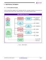
2.2
Cooling
All significant heat generating components are mounted on the top side of the board and are thermally connected
to the thermal solution with thermal pads. The JMM-5000 power supply offers two cooling methods:
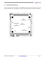
Heat spreader:
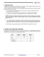
A heat spreader on the top side may be used for all cooling as shown at
the right. The heat spreader is the size and shape of the PC/104 board. It contains the
standard mounting hole patterns for #6 and M3 screws. The
Diamond Systems’ PC/104
heat sink accessory may be installed on top of this heat spreader as an option. When the
heat spreader is installed, the PC/104 and PC/104-
Plus
connectors have bottom-side pins
only and do not support stacking of modules on the top side of the board. The heat spreader
configuration, when attached to a suitable heat dissipation surface or when the heat sink
accessory is installed, supports the full power output at 85
o
C. The heat spreader supports the installation of PC/104
heat sink accessory ACC-HS104-12.7.
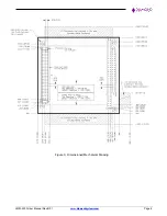
Heat sink:
A low profile heat sink may be installed on the board in the area between the
PC/104 and PC/104-
Plus
connectors as shown at the right. The heat sink should be used
only in applications with power dissipation of 100W or less. The height of the heat sink
conforms to PC/104 height limits of
0.435” / 11mm max height above the PCB top surface.
The heat sink configuration may have a lower total output power capacity at 85
o
C and/or a
lower maximum operating temperature at full power output.
2.3
LED Indicators
A green LED is provided for each output voltage to indicate proper operation. The LEDs are located along the
lower edge of the PCB below the PC/104 connector. All LEDs are calibrated to have equal brightness at the nominal
output voltage for their designated power supply.
2.1
Available Models
Model
5V
20A
12V
8A
3.3V
5A
5V
Standby
3.3V
Standby
ISA
Bus
PCI
Bus
System
Controller
Thermal
JMM-5312-APDRH
Yes
Yes
Yes
Yes
Yes
Yes
Yes
Yes
Heat spreader
JMM-5312-APDRK
Yes
Yes
Yes
Yes
Yes
Yes
Yes
Yes
Heat sink
JMM-5312-ADRH
Yes
Yes
Yes
Yes
Yes
Yes
Yes
Heat spreader
JMM-5312-ADRK
Yes
Yes
Yes
Yes
Yes
Yes
Yes
Heat sink
JMM-5012-APDRH
Yes
Yes
Yes
Yes
Yes
Yes
Heat spreader
JMM-5012-APDRK
Yes
Yes
Yes
Yes
Yes
Yes
Heat sink
JMM-5012-ADRH
Yes
Yes
Yes
Yes
Yes
Heat spreader
JMM-5012-ADRK
Yes
Yes
Yes
Yes
Yes
Heat sink
JMM-5012-APH
Yes
Yes
Yes
Yes
Yes
Heat spreader
JMM-5012-APK
Yes
Yes
Yes
Yes
Yes
Heat sink
JMM-5012-AH
Yes
Yes
Yes
Yes
Heat spreader
JMM-5012-AK
Yes
Yes
Yes
Yes
Heat sink
JMM-5000-APH
Yes
Yes
Yes
Heat spreader
JMM-5000-APK
Yes
Yes
Yes
Heat sink
JMM-5000-AH
Yes
Yes
Heat spreader
JMM-5000-AK
Yes
Yes
Heat sink