


JMM-5000 User Manual Rev B.01
Page 14
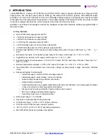
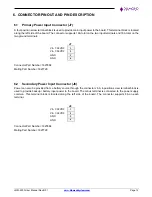
6.5
USB Connector for Control Panel Interface (J12)
A micro USB connector is used for the USB interface to the PIC microcontroller for communication between host
SBC and PIC microcontroller.
1
VBUS
2
D-
3
D+
4
NC
5
Gnd
Part Number: 10118194-0001LF
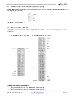
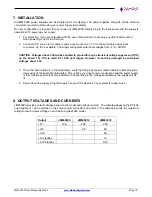
6.6
ISA Connectors (J1 & J2)
For simplicity, signal names are only shown for pins with connections on board. All remaining pins are not used
on JMM-HP.
J2: PC/104 8-bit bus connector
J1: PC/104 16-bit bus connector
A1
B1
Ground
A2
B2
A3
B3
+5V
A4
B4
A5
B5
-5V
A6
B6
A7
B7
-12V
A8
B8
Ground
D0
C0
Ground
A9
B9
+12V
D1
C1
A10
B10
D2
C2
A11
B11
D3
C3
A12
B12
D4
C4
A13
B13
D5
C5
A14
B14
D6
C6
A15
B15
D7
C7
A16
B16
D8
C8
A17
B17
D9
C9
A18
B18
D10
C10
A19
B19
D11
C11
A20
B20
D12
C12
A21
B21
D13
C13
A22
B22
D14
C14
A23
B23
D15
C15
A24
B24
+5V
D16
C16
A25
B25
D17
C17
A26
B26
Ground
D18
C18
A27
B27
Ground
D19
C19
A28
B28
A29
B29
+5V
A30
B30
A31
B31
Ground
Ground
A32
B32
Ground
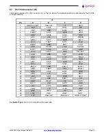
Connector Part Number / Description
J1:
EPT Connectors 962-60323-12
64 pins .435” high solder tails
J2:
EPT Connectors 962-60203-12 40
pins .435” high solder tails