


28
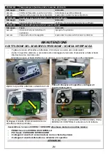
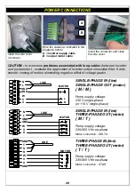
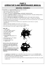
POWER CONNECTIONS
Open the side cover
(4 screws)
Wire the cables as indicated in the
diagrams below:
A = inverter supply cable
B = output motor cable
Insert the connector and close
the side cover.
CAUTION : to overcome problems associated with long cables (between Inverter
and pump motor) , evaluate the application of inverter output sinusoidal filter. It aids
smooth running of motors eliminating negative effect of voltage peaks
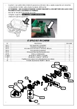
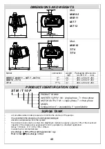
GND
L
N
GND
V
W
U
LINE
MOTOR
N
L
SINGLE-PHASE IN (line)
SINGLE-PHASE OUT (motor)
( M / M )
Pump supply voltage:
230 V single-phase
(or 115 V single-phase)
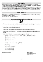
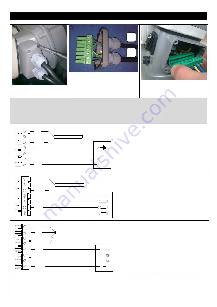
GND
N
L
GND
LINE
MOTOR
U
W
V
SINGLE-PHASE IN (line)
THREE-PHASE OUT (motor)
( M / T )
Pump supply voltage:
230/400 V three-phase
Motor connection : DELTA
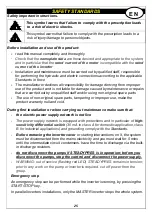
S
V
U
W
GND
R
LINE
T
GND
MOTOR
THREE-PHASE IN (line)
THREE-PHASE OUT (motor)
( T / T )
Pump supply voltage:
230/400 V three-phase
Motor connection : STAR
A
B


