background image

www.dfi.com

11

Chapter 3 Installing Devices

Chapter 3

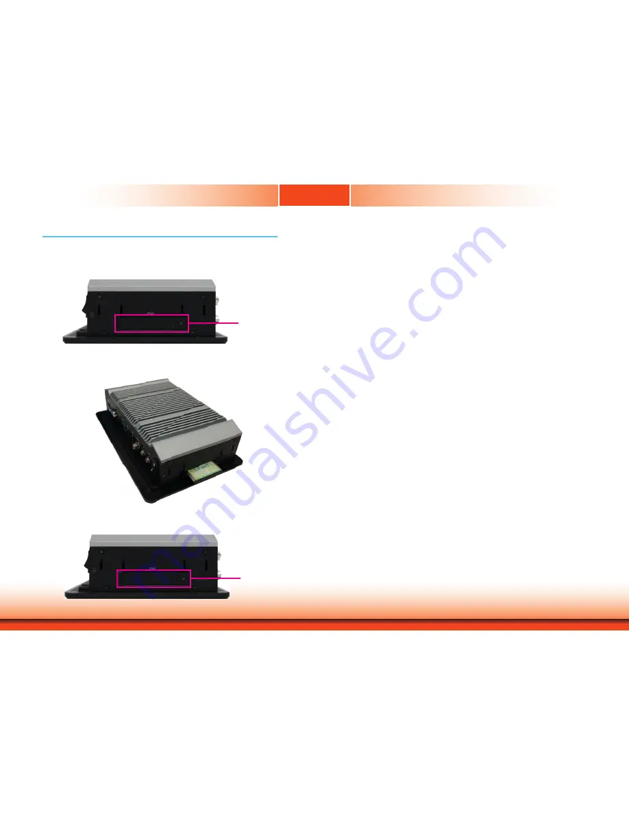
The CFast card slot can be accessed externally without opening the chassis. Before installing a 
CFast card, take off the CFast card slot cover.

Installing a CFast Card

CFast slot cover

1.  Gently insert the CFast card straight with the label on the CFast card facing up until you feel 

it lock into place. Do not force the card into the slot if the card is not correctly inserted.

2.  Close the CFast card cover and attach the screw. To eject the card, push the card inward to 

release the lock and pull it out.

CFast slot cover

Chapter 3 - Installing Devices

Содержание KS070-AL

Страница 1: ...www dfi com 1 Chapter 1 Introduction KS070 AL 7 Touch Panel PC User s Manual A48200809 ...

Страница 2: ... owners FCC and DOC Statement on Class A This equipment has been tested and found to comply with the limits for a Class A digital device pursuant to Part 15 of the FCC rules These limits are designed to provide reason able protection against harmful interference when the equipment is operated in a residential installation This equipment generates uses and can radiate radio frequency energy and if ...

Страница 3: ...a 15 LVDS Channel and bpp Select 15 Auto Power on Select 16 M 2 Signal Select 16 Backlight Power Select 17 Panel Power Select 17 LCD Inverter Power Select 18 Chapter 5 Ports and Connectors 19 Top Panel I O Ports 19 Bottom Panel I O Ports 19 USB Ports 20 COM Serial Ports 21 Graphics Interfaces 22 Audio Output 22 DC in Power Connector 23 RJ45 LAN Ports 23 I O Connectors 24 Serial ATA Connector Seria...

Страница 4: ...igns of physical damage You must take extra care in han dling them to ensure against electrostatic build up 1 To prevent electrostatic build up leave the system board in its anti static bag until you are ready to install it 2 Wear an antistatic wrist strap 3 Do all preparation work on a static free surface 4 Hold the device only by its edges Be careful not to touch any of the components contacts o...

Страница 5: ...system away from humidity Place the system on a stable surface Dropping it or letting it fall may cause damage The openings on the system are for air ventilation to protect the system from overheating DO NOT COVER THE OPENINGS Place the power cord in such a way that it will not be stepped on Do not place anything on top of the power cord Use a power cord that has been approved for use with the sys...

Страница 6: ...GA 1296 Intel Atom x5 E3940 Processor Quad Core 2M Cache 1 6GHz 1 8GHz 9 5W Intel Celeron Processor N3350 Dual Core 2M Cache 1 1GHz 2 4GHz 6W LAN Two LAN ports on the bottom panel COM Two COM ports DB 9 on the top panel Display DP and VGA ports on the bottom panel USB Two USB 2 0 ports type A and two USB 3 0 ports type A Audio Line out and Mic in jacks Side View Bottom View ...

Страница 7: ...EG4 HW Encode H 264 MPEG2 MPEG4 Storage CFast Socket Expansion 1 x Full size Mini PCIe USB PCIe 1 x M 2 2242 B key PCIe USB 2 0 SATA 3 0 Audio Controller Realtek ALC262 Ethernet Controller 2 x Intel I211AT PCIe 10 100 1000Mbps Top I O Ports 2 x RS 232 422 485 DB 9 1 x 8 bit DIO DB 9 available upon request 3 x Wi Fi module antenna holes Bottom I O Ports 2 x GbE RJ 45 10 100 1000Mbps 2 x USB 2 0 typ...

Страница 8: ... microphone DC in Plug a power adapter into this socket LAN Ports Connect a network device or a Ethernet cable for network connectivity USB 3 0 Ports Connect USB 3 0 devices as well as devices from previous versions such as USB 2 0 or USB 1 1 USB 2 0 Ports Connect USB 2 0 or 1 1 devices VGA Port Connects to the VGA port of a display DP Port Connects to the dual mode DisplayPort of a display VGA US...

Страница 9: ...www dfi com 9 Chapter 1 Introduction 75 75 208 50 117 54 127 20 12 25 150 230 58 30 7 50 6 50 80 Chapter 1 Mechanical Dimensions Bottom View Top View Right View Left View Front View ...

Страница 10: ...etup will appear on the screen Press the Delete key to enter the BIOS setup utility Installing an Operating System Depending on the method you choose to install your system you may use a USB flash drive or install a CD ROM drive to run the Operating System CD Make sure that a CFast or an M 2 card is already installed 1 Refer to the following chapters for information on installing a CFast or an M 2...

Страница 11: ...talling a CFast Card CFast slot cover 1 Gently insert the CFast card straight with the label on the CFast card facing up until you feel it lock into place Do not force the card into the slot if the card is not correctly inserted 2 Close the CFast card cover and attach the screw To eject the card push the card inward to release the lock and pull it out CFast slot cover Chapter 3 Installing Devices ...

Страница 12: ...pheral devices connected to it have been powered off 2 Disconnect all power cords and cables 3 The 12 mounting screws on the top and bottom as well as both sides of the system are used to secure the cover to the chassis Remove these screws and put them in a safe place for later use 4 Lift the cover up to open the system Mounting screw Mounting screw Mounting screw Lift the cover upward M 2 socket ...

Страница 13: ... the edge of the M 2 card with the key in the connector 2 Insert the M 2 card into the connector M 2 card 3 Push down on the other end of the M 2 card and secure and card on the mainboard with the provided mounting screw Mounting screw Note The M 2 socket supports PCIe USB and SATA signals and can accommodate common mobile broadband and storage modules For jumper settings on switching the signal b...

Страница 14: ... secure the card on the system board The system board is equipped with one Mini PCIe slot that supports PCIe and USB signals Use the following procedure to install a Mini PCIe card 1 Grasp the Mini PCIe card by its edges and align the notch in the connector of the PCIe card with the key in the connector on the system board Mini PCIe card Mounting screw ...

Страница 15: ... follow these steps below 1 Power off the system and unplug the power cord 2 Set the jumper pins 2 and 3 to On Wait for a few seconds and set the jumper back to its default setting pins 1 and 2 On 3 Now plug the power cord and power on the system 1 2 On Normal default 1 3 2 2 3 On Clear CMOS Data 1 3 2 Chapter 4 Jumper Settings LVDS Channel and bpp Select Switch 1 is used to select the LVDS channe...

Страница 16: ...to power on whenever AC power comes in set JP7 pins 2 and 3 to On If you want to use the power button set pins 1 and 2 to On When using the JP7 Power On feature to power the system back on after a power failure the system may not power on if the power loss is resumed within 5 seconds i e power flicker 1 1 2 910 JP1 LCD Inverter Power Select M 2 Signal Select Backlight Power Select JP1 JP11 JP10 JP...

Страница 17: ...al 1 DC in 1 Audo Power on Select JP7 JP12 1 2 On 12V 6 4 2 5 3 1 3 4 On 5V 6 4 2 5 3 1 5 6 On 3 3V default 6 4 2 5 3 1 Backlight Power Select 1 1 2 910 JP1 LCD Inverter Power Select M 2 Signal Select Backlight Power Select JP1 JP11 JP10 JP10 JP11 Buzzer LAN 1 LAN 2 Mini PCIe M 2 SPI Flash BIOS 1 Clear CMOS Data JP6 2 1 5 6 Front Panel 1 5 6 2 LVDS LCD Panel 1 1 SATA 0 SATA 3 0 1 2 Battery 19 20 1...

Страница 18: ...TA 3 0 1 2 Battery 19 20 1 2 COM 1 2 1 1 ON 2 LVDS Channel and bpp Select SW1 Front Audio 1 9 10 2 Digital I O USB 5 6 1 2 2 1 40 USB 2 0 DP Panel Power Select JP12 Intel WGI211AT USB 1 4 USB 3 0 VGA 1 2 5 SMBus Intel WGI211AT USB 2 3 USB 2 0 DC in USB3 0 Type C OTG SATA Power Standby Power LED SPK OUT 1 1 1 39 1 2 79 80 LCD Inverter Power EIO optional 1 DC in 1 Audo Power on Select JP7 JP11 1 3 2...

Страница 19: ... LAN ports USB 3 0 ports USB 2 0 ports VGA port DP port Bottom Panel I O Ports Chapter 5 Ports and Connectors Antenna holes COM 2 RS232 RS422 RS485 COM 1 RS232 RS422 RS485 The top panel I O consists of the following ports and connectors COM ports COM 1 and COM 2 can be an RS232 RS422 or RS485 port VGA USB 2 0 DP USB 3 0 LAN 2 LAN 1 DC in Mic in Line out Power button ...

Страница 20: ...IO optional 1 DC in DC in DC in USB 4 USB 3 0 USB 1 USB 3 USB 2 USB 2 0 USB 2 0 VCC Data1 Data1 Ground N C VCC Data0 Data0 Ground Key 2 1 9 10 The USB device allows data exchange between your computer and a wide range of simultane ously accessible external Plug and Play peripherals The system board is equipped with 2 onboard USB 3 0 ports USB 1 USB 4 and 2 onboard USB 2 0 ports USB 2 USB 3 The 10 ...

Страница 21: ...d among RS232 422 and 485 The serial ports are asynchronous communication ports with 16C550A compatible UARTs that can be used with modems serial printers remote display terminals and other serial devices Please use the BIOS setup utility to configure serial port communication mode for COM 1 and COM 2 BIOS Setting Configure the serial ports including the serial communication mode in the Advanced C...

Страница 22: ... transmit audio and video simultaneously The interface which is developed by VESA delivers higher performance features than any other digital interfaces Driver Installation Install the graphics driver Refer to Chapter 8 for more information Audio Output Front Audio This Line out jack is used to connect a headphone or external speakers And the MIC in con nector is used to connect an external microp...

Страница 23: ...vity BIOS Setting Configure the onboard LAN in the Advanced menu ACPI Configuration submenu of the BIOS Refer to Chapter 3 for more information Driver Installation Install the LAN drivers Refer to Chapter 7 for more information Connect a DC power cord to this jack Use a power adapter within 12V DC output voltage Using a power adapter that does not conform to the specified voltage may fail to boot ...

Страница 24: ...the other end to your Serial ATA device BIOS Setting Configure the Serial ATA drive in the Advanced menu SATA Configuration submenu of the BIOS Refer to Chapter 7 for more information USB OTG Connector The USB OTG USB 2 0 connector is used for USB communication and it allows the system board and the devices connected to it to switch back and forth between the roles of host and device When the syst...

Страница 25: ...Display Panel Refer to the right side for the pin functions of these connectors BIOS Setting Configure the LCD panel in the Advanced menu Video Configuration submenu of the BIOS Refer to Chapter 7 for more information Pins Function Pins Function 1 GND 2 GND 3 LVDS_Out3 Odd_3 4 LVDS_Out7 Even_3 5 LVDS_Out3 Odd_3 6 LVDS_Out7 Even_3 7 GND 8 GND 9 LVDS_Out2 Odd_2 10 LVDS_Out6 Even_2 11 LVDS_Out2 Odd_2...

Страница 26: ...s Function 1 DIO7 2 DIO6 3 DIO5 4 DIO4 5 DIO3 6 DIO2 7 DIO1 8 DIO0 9 5V 10 GND Digital I O Connector 1 1 2 910 JP1 JP10 JP11 Buzzer LAN 1 LAN 2 Mini PCIe M 2 SPI Flash BIOS 1 Clear CMOS Data JP6 2 1 5 6 Front Panel 1 5 6 2 LVDS LCD Panel 1 1 SATA 0 SATA 3 0 1 2 Battery 19 20 1 2 COM 1 2 1 1 ON 2 Front Audio 1 9 10 2 Digital I O USB 5 6 1 2 2 1 40 USB 2 0 DP Intel WGI211AT USB 1 4 USB 3 0 VGA 1 2 5...

Страница 27: ...ont Audio 1 9 10 2 Digital I O USB 5 6 1 2 2 1 40 USB 2 0 DP Intel WGI211AT USB 1 4 USB 3 0 VGA 1 2 5 SMBus Intel WGI211AT USB 2 3 USB 2 0 USB3 0 Type C OTG SATA Power Standby Power LED SPK OUT 1 1 1 39 1 2 79 80 LCD Inverter Power EIO optional 1 DC in DC in DC in Front Panel HDD_LED SUS_LED Reset_SW PWR_BTN 1 2 5 6 Standby Power LED This LED will light up red when the system is in the standby mod...

Страница 28: ...2 5 SMBus Intel WGI211AT USB 2 3 USB 2 0 USB3 0 Type C OTG SATA Power Standby Power LED SPK OUT 1 1 1 39 1 2 79 80 LCD Inverter Power EIO optional 1 DC in DC in DC in GND 1 SMBus Connector The SMBus System Management Bus connector is used to connect SMBus devices It is a multiple device bus that allows multiple chips to connect to the same bus and enable each one to act as a master by initiating d...

Страница 29: ...he wall mount kit includes the following 2 wall mount brackets Bracket screws 1 Before starting any installation procedure attach the poron foam to the Panel PC 2 Select a place on the wall where you will mount the Panel PC 3 Use the provided mounting screws to attach wall mount bracket 1 to the wall 4 Attach the other bracket wall mount bracket 2 to the rear of the Panel PC Wall mount bracket 1 M...

Страница 30: ... mount bracket 1 to attach the two brackets with the hooks Then tighten the screw to secure the assembly in place Screw 2 Select a place on the panel or wall where you will mount the Panel PC 3 Cut out a shape on the panel that corresponds to the Panel PC s rear dimensions 210 5mm x 132 2mm and ensure that the Panel PC can be fitted into the panel properly Panel Mounting hole 132 20 210 50 5 1 Bef...

Страница 31: ... them into the slits around the Panel PC Slit for mounting the clamp Mounting clamp White plastic cap 6 The first and second clamps must be positioned and secured diagonally prior to mounting the rest of the clamps Tighten the clamp s screw using an electric screwdriver by pressing the white plastic cap onto the back of the panel The illustration below shows that all clamps are properly mounted 13...

Страница 32: ...un After you power up the system the BIOS message appears on the screen and the memory count begins After the memory test the message Press DEL to run setup will appear on the screen If the message disappears before you respond restart the system or press the Reset button You may also restart the system by pressing the Ctrl Alt and Del keys simultaneously Note The BIOS is constantly updated to imp...

Страница 33: ...our system or let you set some features according to your preference Important Setting incorrect field values may cause the system to malfunction System Time The time format is hour minute second The time is based on the 24 hour military time clock For example 1 p m is 13 00 00 Hour displays hours from 00 to 23 Minute displays minutes from 00 to 59 Second displays seconds from 00 to 59 System Date...

Страница 34: ...hics Resource Table mechanism CPU Configuration This section configures the CPU EIST Enable or disable the Enhanced Intel SpeedStep Technology which helps optimize the balance between system s power consumption and performance After it is enabled in the BIOS you can take advantage of its offering by setting power schemes from the operating system s power options Turbo Mode Enable or disable proces...

Страница 35: ...nel type and the panel color depth options will be shown LCD Panel Type Select the type of LCD panel connected to the system s LCD connector Please check the specification of your LCD monitor Panel Color Depth Select the LCD panel color depth 18 bit 24 bit 36 bit and 48 bit Audio Configuration This section configures the audio settings HD Audio Control the detection of the high definition audio de...

Страница 36: ...ed from these options Gen1 1 5 Gbit s Gen2 3 Gbit s or Gen 3 6 Gbit s SATA Mode Selection The mode selection determines how the SATA controller s operates AHCI Mode This option allows the Serial ATA devices to use AHCI Advanced Host Controller Interface Serial ATA Port 0 and 1 and Hot Plug Enable or disable each Serial ATA port and its hot plug function SATA Port 0 It controls the signal of the CF...

Страница 37: ...the board PCI Express Configuration This section configures the settings of PCI Express root ports PCI Express Root Port 1 Controls the PCIe signal of the M 2 slot PCI Express Root Port 3 Controls the PCIe signal of LAN Port 1 PCI Express Root Port 4 Controls the PCIe signal of LAN Port 2 PCI Express Root Port 5 Controls the PCIe signal of Mini PCIe slot Press Enter to enter the configurations for...

Страница 38: ...ystem from a remote station by re direct ing the host screen output through a serial port Console Serial Redirect Enable or disable the console redirection function The default is disabled If you select to enable it please configure the following parameters for serial communication be tween the system and a remote station Terminal type VT_100 VT_100 VT_UTF8 or PC_ANSI Baud rate 115200 57600 38400 ...

Страница 39: ...each serial port COM Port 1 and COM Port 2 Enable or disable each serial port Disable Disable this serial port Enable Enable this serial port It also shows the Base I O address and the assigned interrupt number Type Choose RS232 RS422 or RS485 Peer to Peer for the serial port type for COM port 1 and 2 WDT Enable or disable the watchdog function A counter will appear if you select to enable WDT Inp...

Страница 40: ...lability and its configurations TPM Operation Select one of the supported operation to change the TPM2 state Clear TPM Remove all TPM ownership contents Set Supervisor Password Set the administrative password for entering the BIOS utility or upon the entering of the power on self test POST process The length of the password must be greater than 1 character and less than or equal to 10 characters ...

Страница 41: ...disable network stack It supports the operation of these functions or soft ware Windows 8 BitLocker Network Unlock and UEFI IPv4 IPv6 PXE PXE Boot Capability Enable or disable Preboot eXecution Environment PXE boot through the Ethernet This function can only be enabled if the Network Stack support is enabled USB Boot Enable or disable USB boot from a flash drive Note The BIOS supports only UEFI bo...

Страница 42: ...IOS setup without saving your changes Save Setting to file Select this option to save BIOS configuration settings to a USB drive The operation will fail if there aren t any USB devices detected on the system The saved configuration will have the DSF file extension and can be used for restoration Restore Setting from file Select this option to restore BIOS configuration settings from a USB drive No...

Страница 43: ...used on another system board of the same model 2 The BIOS SPI ROM on this system board must be the original equipment from the factory and cannot be used to replace one which has been utilized on other system boards 3 If you do not follow the methods above the Intel Management Engine will not be updated and will cease to be effective Note a You can take advantage of flash tools to update the defau...

Страница 44: ...ions required to enhance the performance of the system board Insert the CD into a CD ROM drive The auto run screen the Utility and Manual CD will ap pear If the Auto run does not automatically start please go directly to the root directory of the CD and double click Setup Auto Run Page For Windows 10 Chapter 8 Supported Software ...

Страница 45: ...stall the utility click Intel Chipset Software Installation Utility in the main menu 1 Setup is ready to install the utility Click Next to continue 2 Read the license agreement then click Accept if you accept the terms and condi tions 4 After the installation is com plete click Restart Now Restarting the system will allow the new software installation to take effect 3 Go through the readme docu me...

Страница 46: ... is running before the Windows 7 Windows 8 desktop appears The blank screen period is the time Windows is testing the graphics perfor mance We recommend that you skip this process by disabling this function and click Next 2 Read the license agreement then click Yes if you accept the terms and conditions 4 Setup is now installing the driver Click Next to continue 3 Go through the Readme docu ment f...

Страница 47: ...tall the driver Click Next to continue 2 Click I accept the terms in the license agreement if you accept the terms and conditions then click Next 3 Select the program features you want to install then click Next to continue 4 Click Install to begin the installation 5 After the installation is complete click Finish to exit the setup program ...

Страница 48: ...er click Intel TXE Drivers in the main menu 1 Select I accept the terms in the License Agreement then click Next 2 The screen shows the compo nents that will be installed Click Next to continue 3 The screen displays the installation status in progress 4 Click Finish when the installation is complete ...

Страница 49: ...dio Drivers To install the driver click Realtek Audio Drivers in the main menu 2 Follow the on screen instruc tions to proceed with the setup program Click Next each time you finish a step IO Driver To install the Intel Serial IO driver click IO Driver in the main menu 1 Setup is ready to install the driver Click Next to continue 2 Read the license agreement carefully Click I accept the terms in t...

Страница 50: ...are Chapter 8 3 Read the file information for instal lation information then click Next 4 Setup is ready to install the driver Click Next to begin the installation 5 Setup is now installing the driver 6 Click Finish to exit setup ...

Страница 51: ...l the driver Click Next to continue 2 Read the license agreement care fully Click I accept the terms of the license agreement if you agree with the terms in the agreement then click Next 3 Setup detects that an extra RS232 interface driver needs to be installed for the eGalaxTouch controller Please check to install the driver 4 Select the setup type that best suits your needs ...

Страница 52: ... installation folder Follow the rest of the steps on the screen to complete the installation proce dure Wi Fi Driver To install the Wi Fi driver click WLAN Driver in the main menu 1 Select the language for the instal lation 2 Setup is now ready to install the audio driver Click Next to start the installation ...

Страница 53: ...ted Software Chapter 8 3 Read the license agreement care fully Click I accept the terms of the license agreement if you agree with the terms in the agreement then click Next 4 Click Finish to exit the installation wizard ...

Отзывы: