background image

54

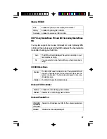
System Error Report

When the BIOS encounters an error that requires the user to correct
something, either a beep code will sound or a message will be dis-
played in a box in the middle of the screen and the message PRESS
F1 TO CONTINUE, CTRL-ALT-ESC or DEL TO ENTER SETUP, will be
shown in the information box at the bottom. Enter Setup to correct the
error.

POST Beep

There are two kinds of beep codes in the BIOS. One code indicates
that a video error has occured and the BIOS cannot initialize the video
screen to display any additional information. This beep code consists of
a single long beep followed by three short beeps. The other code indi-
cates that a DRAM error has occured. This beep code consists of a
single long beep.

Error Messages

One or more of the following messages may be displayed if the BIOS
detects an error during the POST. This list indicates the error messages
for all Awards BIOSes:

CMOS BATTERY HAS FAILED

The CMOS battery is no longer functional. It should be replaced.

CMOS CHECKSUM ERROR

Checksum of CMOS is incorrect. This can indicate that CMOS has be-
come corrupt. This error may have been caused by a weak battery.
Check the battery and replace if necessary.

DISPLAY SWITCH IS SET INCORRECTLY

The display switch on the motherboard can be set to either mono-
chrome or color. This indicates the switch is set to a different setting
than indicated in Setup. Determine which setting is correct, then either
turn off the system and change the jumper or enter Setup and change
the VIDEO selection.

Содержание G586SPB AIO

Страница 1: ...G586SPBAIO Rev A SystemBoard User sManual 32060802 ...

Страница 2: ...e the receiving antenna Increase the separation between the equipment and the receiver Connect the equipment into an outlet on a circuit different from that to which the receiver is connected Consult the dealer or an experienced radio TV technician for help Notice 1 The changes or modifications not expressly approved by the party responsible for compliance could void the user s authority to oper a...

Страница 3: ...on 17 Jumper Settings for CPUs 18 Installing Upgrade CPUs 20 Jumper Settings for Password Clear 23 Jumper Settings for Display Type 23 Jumper Settings for PS 2 Mouse 24 Jumper Settings for Internal External Battery 24 Built in Ports 25 Serial Ports 25 PS 2MousePort 26 Parallel Port 26 Floppy Disk Drive Controller 27 IDE Hard Disk Interface 27 VGAPort 29 Installing Expansion Cards 29 Chapter 3 Soft...

Страница 4: ...Password 49 UserPassword 49 IDEHDDAutoDetection 50 HDDLowLevelFormat 52 Save Exit Setup 53 Exit Without Saving 53 System Error Report 54 Driver Installation 55 Chapter4 TroubleshootingChecklist 56 AppendixA TypesofModules 60 AppendixB MemoryandI OMaps 61 AppendixC Connectors 63 ...

Страница 5: ...troller can display graphic resolutions up to 1024x768 256 colors with 1MB DRAM and up to 1280x1024 256 colors with 2MB DRAM The built in VGA function also supports VESA DDC1 and DDC2B Plug and Play monitors The G586SPB AIO design is based on the Peripheral Component Inter connect PCI local bus and Industry Standard Architecture ISA stan dards It is equipped with 3 dedicated PCI slots and 4 dedica...

Страница 6: ... upgradeable with a 256KB cache module for a maximumof512KBcache SYSTEMMEMORY 8MBto256MBmemory Four 72 pin SIMM sockets Unified Memory Architecture 64 bit main memory is shared between the CPU and the graphics controller Uses EDO or fast page mode x32 DRAM 60ns or 70ns BIOS Award BIOS Windows 95 Plug and Play compatible FlashEPROMforeasyBIOSupgrades ENERGYEFFICIENTDESIGN Systempowermanagementsuppo...

Страница 7: ...ional PCIIDEINTERFACE Supports fast Mode 3 and Mode 4 Enhanced IDE DMAMode2BusMasterIDE Two IDE connectors to control four drives e g two HDDs one tape driveandoneCD ROM Bus mastering reduces CPU use during disk transfer ATAPIIDECD ROMsupported INTEGRATEDI O Two NS16C550A compatible enhanced serial ports One SPP ECP EPP parallel port Supports 360KB 720KB 1 2MB 1 44MB and 2 88MB floppy drives OneIr...

Страница 8: ...G586SPBAIOsystemboard The G586SPB AIO user s manual One 40 pin IDE hard disk cable One 34 pin floppy disk drive cable One 25 pin printer port cable for chassis mounting One card edge bracket with serial and mouse port cables One card edge bracket with an analog VGA port cable One IDE driver diskette One set of VGA driver diskettes Cache module optional If any of these items are missing or damaged ...

Страница 9: ...rpeted floors These areas also attract static electricity which can damage some circuits on your system board Make sure the power source has a properly grounded three pronged socket It is essential that the power connection be properly grounded for correct functioning of your system board For further protection we recommend that you use a surge suppressor This will protect the sys tem board from d...

Страница 10: ...r disk drives add in boards and other components Perform the upgrade instruction procedures described at an ESD workstation only If such a station is not available you can provide some ESD protection by wearing an anti static wrist strap and attaching it to a metal part of the system chassis If a wrist strap is unavailable establish and maintain contact with the system chassis throughout any proce...

Страница 11: ...refer to the handling instructions on pages 9 10 for proper handling tech niques 6 Insert the memory modules into the memory banks on the G586SPB AIO The quantity and location of the memory modules depends on the memory configuration and type of modules you in tend to use 7 Insert the cache module if any into the cache module slot on the G586SPB AIO Refer to the Cache Memory section for upgrading ...

Страница 12: ...12 BoardLayout square denotes pin 1 ...

Страница 13: ...banks Bank 0 or Bank 1 but you must populate one bank first before going to the next bank The G586SPB AIO system board can support 8MB to 256MB of memory using 1MBx32 2MBx32 4MBx32 8MBx32 or 16MBx32 72 pin SIMMs The table below shows the supported SIM modules and their corresponding memory sizes The table below summarizes the bank locations and modules needed for the corresponding memory sizes Mem...

Страница 14: ...6MBx32 16MBx32 MemorySize 32MB 32MB 32MB 40MB 40MB 48MB 48MB 64MB 64MB 64MB 72MB 72MB 80MB 80MB 96MB 96MB 128MB 128MB 128MB 136MB 136MB 144MB 144MB 160MB 160MB 192MB 192MB 256MB Bank0 SIMM3 4MBx32 2MBx32 1MBx32 4MBx32 2MBx32 4MBx32 8MBx32 4MBx32 1MBx32 8MBx32 2MBx32 8MBx32 4MBx32 8MBx32 16MBx32 8MBx32 1MBx32 16MBx32 2MBx32 16MBx32 4MBx32 16MBx32 8MBx32 16MBx32 16MBx32 SIMM2 4MBx32 2MBx32 4MBx32 1M...

Страница 15: ...r 512KB cache mounted at locations U4 and U6 of the system board If your system board is mounted with 256KB cache you may upgrade your cache memory to 512KB by installing a 256KB cache module in the 160 pin cache module slot KM1 Regardless of the amount of cache memory installed one SRAM is mounted on loca tion U8 for tag RAM to store the cacheable addresses Refer to page 12 for the locations of t...

Страница 16: ... 1 2On 2 3On 2 3On JumpersJP2 JP4andJP5 Cache Size Select Installing the Cache Module Locate the 160 pin cache module slot on the system board KM1 Posi tion the cache module above the slot Make sure pin 1 of the cache module is aligned with pin 1 of the slot Carefully slide the module into the slot Press firmly on the top of it to seat it properly 1 2 3 1 2 3 1 2On 2 3On ...

Страница 17: ...ers to move the jumpers if necessary CacheableRange CacheableMemory 256KB 512KB 8 bitsTag 64MB 128MB 7 bitsTag 1 Dirty Bit 32MB 64MB CacheSize The L2 WB Tag Bit Length category in the Chipset Features Setup of the Award BIOS Setup utility allows you to set the Tag Bit Length to 7 bits or 8 bits The default setting is 7 bits This setting will in crease the performance of your system but the cacheab...

Страница 18: ...V VR STD If the voltage of your CPU is not 3 3V make sure you set JP10 JP11 and JP12 according to the voltage of your CPU otherwise your system will hang CPU Voltage 2 7V 2 8V 2 9V 3 3V VR STD 3 5V VRE JP10 1 2 On 3 4 On 5 6 On All Off All Off JP11 1 2 On 1 2 On 1 2 On 3 4 On 5 6 On 7 8 On 3 4 On 5 6 On 7 8 On JP12 1 2 On 1 2 On 1 2 On 1 2 On 3 4 On CPU Speed 75MHz 90 120 150MHz 100 133 166 200MHz...

Страница 19: ...LK 25MHz 30MHz 33 3MHz Pins 1 2 Off On Off Pins 3 4 On Off Off Pins 5 6 Off Off Off JP6 CPU P Rate Internal External Freq Speed 75 75 50 90 90 60 100 100 66 1 5x 2x for future CPUs JP14 2 3 On 1 2 On JP13 Off Off AMD K5CPUs JP6 1 3 5 4 6 2 JP12 JP11 JP10 1 3 5 4 6 2 1 3 5 7 2 4 6 8 3 1 4 2 JP1 Off Off Off Warning The default setting of JP10 JP11 and JP12 is 3 3V If the voltage of your CPU is not 3...

Страница 20: ...ore proceeding with the upgrade take note of the following The micropro cessor and heatsink may be hot if the system has been running To avoid the possibility of a burn power the system off and let the proces sor and heatsink cool for 20 minutes The 321 pin ZIF socket consists of five rows of pin holes on each side To prevent improper CPU installation the ZIF socket has a Plug Keying mechanism Sev...

Страница 21: ... their corresponding holes Remember that very little force is needed to install the CPU If the CPU is not easily inserted verify whether or not pin 1 of the CPU is aligned with pin 1 of the socket Applying too much pressure can damage the CPU or the socket amount of sideways force to free the handle from its retaining tab Once clear of the tab the handle will open relatively easily The top plate w...

Страница 22: ...ted on top To maintain proper airflow once the upgrade is installed on the system board the CPU and heatsink require certain space clearances The clearance above the CPU s fan heatsink must be at least 0 4 inches The clearance on at least 3 of 4 sides of the processor and heatsink must be at least 0 2 inches All cables for floppy drive hard drive CD ROM etc must be routed clear of the CPU and its ...

Страница 23: ...t off again This will clear the password stored in your CMOS Set JP9 back to its default setting pins 1 and 2 On 1 2 On Normal default 2 3 On Password Clear 1 2 3 1 2 3 JumperSettingsforDisplayType JumperJP15 Display Type Select Jumper JP15 sets the display adapter to color or mono This jumper must match the type of display adapter installed If you changed your video adapter make sure this jumper ...

Страница 24: ...7 to On to use the lithium battery If you are connecting an external battery to connector J19 you must set JP17 to Off On InternalBattery Off ExternalBattery default JumperSettingsforPS 2Mouse JumperJP16 PS 2Mouse The G586SPB AIO package includes a card edge bracket with two se rial ports and a mouse port By default the PS 2 mouse port is enabled The PS 2 mouse port uses IRQ12 but when the PS 2 mo...

Страница 25: ...ations of the built in connectors and pin 1 of those connec tors Serial Ports The built in serial ports are RS 232C asynchronous communication ports with 16C550A compatible UARTs that can be used with modems serial printers remote display terminals and other serial devices They use the following system I O addresses PortConfiguration Serial Port 1 Serial Port 2 COM1 3F8h 3F8h COM2 2F8h 2F8h COM3 3...

Страница 26: ...o the system chassis PS 2MousePort The PS 2 mouse port is a 6 pin connector on the system board Attach the 6 pin mouse port cable which is mounted on the card edge bracket to connector J15 Make sure the brown wire on the PS 2 mouse con nector is aligned with pin 1 of connector J15 Parallel Port The G586SPB AIO system board has a standard connector for interfac ing your PC to a parallel printer The...

Страница 27: ...e of the daisy chained ribbon cable with pin 1 of the drive edge connector s The end most connector should be attached to the drive you want to designate as Drive A IDE Hard Disk Interface The G586SPB AIO system board is equipped with two PCI IDE shrouded headers that will interface four Enhanced IDE Integrated Drive Electronics hard disk drives Note Only Enhanced IDE hard drives or ATAPI CD ROMs ...

Страница 28: ...tor CON1 2 Install the other 40 pin header connector s into the device with the colored edge of the ribbon cable aligned with pin 1 of the drive edge connector s Note Refer to your disk drive user s manual for information about selecting proper drive switch settings AddingaSecondIDEHardDrive When using two IDE drives one must be set as the master and the other as the slave Follow the instructions ...

Страница 29: ...ve VGAPort One card edge bracket mounted with an analog VGA port cable is pro vided with the system board Connect the VGA port cable to connector J3 on the system board Make sure the colored stripes on the ribbon cable is aligned with pin 1 of connector J3 Mount the card edge bracket tothesystemchassis Installing Expansion Cards The G586SPB AIO system board is equipped with 3 dedicated PCI slots a...

Страница 30: ...rl Alt and Del keys simultaneously If you have set a password and selected System in the Security Op tion of the BIOS Features Setup menu you will be prompted for the password every time the system is rebooted or any time you try to enter Setup Type in the correct password and press Enter If you selected Setup in the Security Option you will be prompted for the password only when you try to enter ...

Страница 31: ...POWER MANAGEMENT SETUP PNP PCI CONFIGURATION LOAD BIOS DEFAULTS LOAD SETUP DEFAULTS INTEGRATED PERIPHERALS SUPERVISOR PASSWORD USER PASSWORD IDE HDD AUTO DETECTION HDD LOW LEVEL FORMAT SAVE EXIT SETUP EXIT WITHOUT SAVING ESC F10 Quit Sve Exit Setup Shift F2 Select Item Change Color Time Date Hard Disk Type ROM PCI ISA BIOS STANDARD CMOS SETUP AWARD SOFTWARE INC Date mm dd yy Wed Jul 24 1996 Time h...

Страница 32: ...e categories allow you to enter the appropriate specifications for the type of hard disk drive s installed in your system There are 45 predefined types and 4 user definable types for hard drives Type 1 to Type 45 are predefined Type User is user definable Press PgUp or PgDn to select a numbered hard disk type or type the number and press Enter The hard disk will not work properly if you enter impr...

Страница 33: ...1 2megabytecapacity 3 1 2 inch double sided drive 720 kilobyte capacity 3 1 2 inch double sided drive 1 44 megabyte capacity 3 1 2 inch double sided drive 2 88 megabyte capacity If the controller of the HDD interface is ESDI you must select Type 1 If the controller of the HDD interface is SCSI you must select None If you select Type Auto the BIOS will auto detect the HDD CD ROM drive at the POST s...

Страница 34: ...rmines whether the system will stop if an error is de tected during power up The default setting is All Errors BIOS default Setup default NoErrors All Errors All But Keyboard All But Diskette All But Disk Key The system boot will not stop for any errors detected The system boot will stop whenever the BIOS detects a non fatal error The system boot will not stop for a keyboard error it will stop for...

Страница 35: ... basic operation Some entries are defaults required by the system board while others if enabled will improve the performance of your system or let you set some features according to your preference Base Memory Extended Memory Other Memory This refers to the amount of base or conventional memory installed on the system board This is the amount of memory located above 1MB in the memory address map o...

Страница 36: ...stemmaynotinstallnorwork BIOS issues a warning when any program or virus sends a Disk Format command or attempts to write to the boot sector of the hard disk drive No warning message will appear when the hard disk drive is accessed Enabled Disabled CPUInternalCacheandExternalCache These categories speed up the memory access However it depends on the CPU chipset design The default value is enabled ...

Страница 37: ... the system is booting from the floppy drive the system will boot from drive A Enabled Disabled BootUpFloppySeek During POST the BIOS will determine if the floppy disk drive installed is 40 or 80 tracks 360K type is 40 tracks while 760K 1 2M and 1 44M are all 80 tracks The BIOS will check whether the floppy disk drive installed is 40 or 80 tracks Note that the BIOS cannot distinguish be tween 720K...

Страница 38: ...stem will not boot and access to Setup will be denied if the correct password is not entered at the prompt The system will boot but access to Setup will be denied if the correct password is not entered at the prompt System Setup PCI VGAworkingwithMPEGISA VESAVGAcards PCI VGAnotworkingwithMPEGISA VESAVGAcards Enabled Disabled PCI VGAPaletteSnoop This is used to select whether to allow MPEG ISA VESA...

Страница 39: ...et manages bus speeds and access to system memory resources such as DRAM and external cache It also coordinates communications between the conventional ISA bus and the PCI bus These items should not be altered unless necessary Depend ing on your add in boards you may not or should not enable some of those features The default settings have been chosen because they provide the best operating condit...

Страница 40: ... CPU PCI Burst Mem Write CPU PCI Post Mem Write VGA Shared Memory Size VGA Memory Clock MHz Enabled Enabled Disabled 3 CK 1 CK Enabled Enabled 1 MB 55 AutoConfiguration Enabled Disabled The system will set the DRAM RAS to CAS delay to the ISA Bus Clock Frequency categories automatically This allows you to set the DRAM RAS to CAS delay to the ISA Bus Clock Frequency categories manually ISABusClockF...

Страница 41: ...e Disable Standby Mode Disable Suspend Mode Disable PM Events COM Ports Activity Enable LPT Ports Activity Enable HDD Ports Activity Disable PCI ISA Master Act Enable IRQ 1 15 Activity Enable PowerManagement This category allows you to select the type or degree of power saving by changing the length of idle time that elapses before each of the following modes are activated Doze Mode Standby Mode a...

Страница 42: ...rite blanks to the video buffer This option only writes blanks to the video buffer Initializes display power management signaling V H SYNC Blank Blank Screen DPMS SuspendSwitch Enable Disable Enables the Green switch connector J13 To use the Green switch connector make sure to set this category to Enable Disables the Green switch connector J13 Doze Speed div by and Standby Speed div by This is use...

Страница 43: ...em inactivity all devices except the CPU will be shut off It is used to define the continuous HDD idle time that elapses before the HDD enters the power saving mode motor off When enabled and after the set time of system inactivity the hard disk drive will be powered down while all other devices remain active PMEventsandIRQ3 IRQ15 These are I O events whose occurrence can prevent the system from e...

Страница 44: ...2 Select Item Modify Color PCI IRQ Active By Level PCI IDE 2nd Channel Disabled PCI IDE IRQ Map To PCI AUTO Primary IDE INT A Secondary IDE INT B PCI Spec Ver 2 1 Enabled ResourcesControlledBy The Award Plug and Play BIOS has the capacity to automatically con figure all of the boot and Plug and Play compatible devices However this capability means absolutely nothing unless you are using a Plug and...

Страница 45: ...oller card is designated as the secondary IDE controller No IDE controller card occupying any of the PCI slots Enabled Disabled PCIIDEIRQMapTo This category is used to configure your system to the type of IDE disk controller in use ISA PCI Auto DesignatestheISAslotthatisinstalledwithanIDEcontroller card thatis ifyouareusinganIDEcontrollercard ThesystemwillscananddeterminethePCIslotthatisin stalled...

Страница 46: ...e Setup default values as standard values for your system Highlight this option on the main menu and press Enter The mes sage below will appear Load Setup Defaults Y N N Type Y and press Enter to load the Setup default values Integrated Peripherals ROM PCI ISA BIOS INTEGRATED PERIPHERALS AWARD SOFTWARE INC Internal PCI IDE IDE Primary Master PIO IDE Primary Slave PIO IDE Secondary Master PIO IDE S...

Страница 47: ...fer in timing When Auto is selected the BIOS will select the best available mode after checking your hard drive IDEHDDBlockMode Enabled Disabled The IDE HDD uses the block mode The system BIOS will check the hard disk drive for the maximum block size the system can transfer The block size will depend on the type of hard disk drive The IDE HDD uses the standard mode OnboardFDDController Enables the...

Страница 48: ... The G586SPB AIO system board supports IrDA function for wireless connectivity between your computer and peripheral devices To use the IrDA function follow the steps below 1 Connect your IrDA cable to connector J11 of the G586SPB AIO system board Refer to page 12 for the location of connector J11 2 Set UART 2 Mode to the type of IrDA standard supported by your computer You may not use IrDA J11 and...

Страница 49: ...appear ConfirmPassword You are asked to verify the password Type in exactly the same pass word If you type in a wrong password you will be prompted to enter the correct password again To delete or disable the password function highlight Supervisor Pass word and press Enter instead of typing in a new password Press the Esc key to return to the main menu If you forget your password you should clear ...

Страница 50: ...ITY AWARD SOFTWARE INC HARD DISKS TYPE SIZE CYLS HEAD PRECOMP LANDZ SECTOR MODE Primary Master Select Primary Master Option N Skip N OPTIONS 1 Y Note Some OSes like SCO UNIX must use NORMAL for installation ESC Skip SIZE 345 MODE NORMAL SECTOR 57 LANDZ 789 PRECOMP 65535 HEAD 15 CYLS 790 Enter your choice and press Enter to accept the parameters or press Esc to abort The parameters of the hard disk...

Страница 51: ...ough the physical size of the HDD may be greater than that LBA Logical Block Addressing Mode The LBA mode is a HDD accessing method to overcome the 528 mega byte limitation The number of cylinders heads and sectors shown on the screen may not be the actual number for the HDD During HDD accessing the IDE controller will transform the logical ad dress described by the sector head and cylinder number...

Страница 52: ...rs without LBA support in some cases you may not want the LBA mode This system board provides another alternative to support these kinds of HDDs The BIOS tells the operating system that the number of cylinders is half the actual number and that the number of heads is double the actual number During disk access the reverse conversion is done by the INT13h routine MaximumHDDsize no Cylinders 1024 x ...

Страница 53: ...once again see the initial diagnostics on the screen If you wish to make additional changes to the setup press Ctrl Alt Esc simul taneously or Del after memory testing is done ExitWithoutSaving Whenyoudonotwanttosavethechangesyouhavemade highlight Exit WithoutSaving andpress Enter Themessagebelowwillappear Quit Without Saving Y N N Type Y and press Enter The system will reboot and you will once ag...

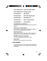
Страница 54: ...that a DRAM error has occured This beep code consists of a single long beep ErrorMessages One or more of the following messages may be displayed if the BIOS detects an error during the POST This list indicates the error messages for all Awards BIOSes CMOSBATTERYHASFAILED The CMOS battery is no longer functional It should be replaced CMOSCHECKSUMERROR Checksum of CMOS is incorrect This can indicate...

Страница 55: ...eyboard error or no keyboard present Cannot initialize the keyboard Make sure the keyboard is attached cor rectly and no keys are being pressed during the boot ManufacturingPOSTloop System will repeat POST procedure infinitely while the keyboard con troller is pull low This is also used for M B burn in test at the factory BIOSROMchecksumerror Systemhalted The checksum of ROM address F0000H FFFFFH ...

Страница 56: ...rking 4 Test the outlet by plugging in a lamp or other electrical device 5 The monitor is turned on 6 The display s brightness and contrast controls are adjusted properly 7 All add in boards in the expansion slots are seated securely 8 Any add in boards you have installed is designed for your system and is set up correctly Monitor Display The display screen remains dark after the system is turned ...

Страница 57: ...AC power cord is plugged into a live outlet and the other end properly plugged into the back of the system 2 Make sure that the voltage selection switch on the back panel is set for the correct type of voltage you are using 3 The power cord may have a short Inspect the cord and install a new one if necessary FloppyDrive The computer cannot access the floppy drive 1 The floppy diskette may not be f...

Страница 58: ...turned on and that the printer is on line 2 Make sure your software is configured for the right type of printer attached 3 Verify that the onboard LPT port s I O address and IRQ settings are configured correctly 4 Verify that the attached device works by attaching it to a parallel port that is working and configured correctly If it works the printer can be assumed to be in good condition If the pr...

Страница 59: ...re there are no objects resting on the keyboard and that no keys are pressed during the booting process SystemBoard 1 Make sure the add in card is seated securely in the expansion slot If the add in card is loose power off the system re install the card and power up the system 2 Check the jumper settings to ensure that the jumpers are properly set 3 Verify that all SIMMs are seated securely into t...

Страница 60: ...Bx32 4MBx32 8MBx32 16MBx32 Brand Fujitsu OKI OKI NEC Micron TI Micron Micron NEC Hitachi Fujitsu Mitsubishi Hitachi NEC NEC NEC LGS ChipNumber 81C1000A 70 M51440A 70 M511000B 70 424400 60 40447 60 TMS4400DJ 70 MT4C4007 70 EDO MT4C4007 60 EDO 4218165 60 EDO 7400AS 70 8117400 70 422A06 70 5117400AS 70 4217400 60 4217405 70 EDO 4217405 60 EDO GM71C16100AT 60 ...

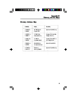
Страница 61: ...RAM 00A0000to 128KBVideo Reserved for Graphics 00BFFFF DisplayMemory DisplayMemory 00C0000to 160KBI O ReservedforROMon 00E7FFF ExpansionROM I OAdapterCard 00E8000to 96KBROMon SystemBoardBIOS 00FFFFF theSystemBoard 0100000to Maximum SystemBoardMemory FFFFFFF Memory256MB AppendixB MemoryandI OMaps ...

Страница 62: ...t Controller 2 8259A 000C0 000DF DMA Controller 2 8237A 5 000E8 ShadowRAMandCacheControlBit 000F0 ClearNumericProcessor ExtensionBusy 000F1 Reset Numeric Processor Extension 000F8 000FF Numeric Processor Extension 001F0 001F8 FixedDisk 00200 00207 GameI O 00278 0027F Parallel Printer Port 2 002F8 002FF Serial Port 2 00300 0031F PrototypeCard 00360 0036F Reserved 00378 0037F Parallel Printer Port 1...

Страница 63: ...onnector TurboLEDconnector Secondary serial connector Parallel printer port IrDA connector Turbobuttonconnector Greenswitchconnector Primary serial connector PS 2mouseconnector Resetswitchconnector Speakerconnector PowerLED Keylock External battery connector Secondary IDE hard didk drive connector Primary IDE hard disk drive connector PS 2 keyboard connector ATkeyboardconnector Powerconnector Cach...

Страница 64: ...Signal J13 Greenswitchconnector Pin 1 2 Function Signal Ground J16 Reset switch connector Pin 1 2 Function Ground Reset J11 IrDAconnector Pin 1 2 3 4 5 Function IrTX Ground IrRX N C VCC J17 Speakerconnector Pin 1 2 3 4 Function Signal Reserved Ground 5V J19 External battery connector Pin 1 2 3 4 Function External battery Key N C Ground J18 PowerLED Keylock Pin 1 2 3 4 5 Function PowerLED Reserved ...

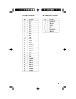
Страница 65: ...20 21 22 23 24 25 26 Function PD0 PD1 PD2 PD3 PD4 PD5 PD6 PD7 Pclk Blank HSync VSync NotUsed Ground Ground Ground Video Sync Dclk NotUsed Ground Ground Ground Ground NotUsed NotUsed J15 PS 2mouseconnector Pin 1 2 3 4 5 6 Function MouseData Reserved Ground 5V MouseClock Reserved ...

Отзывы: