64
4
Jumper Settings
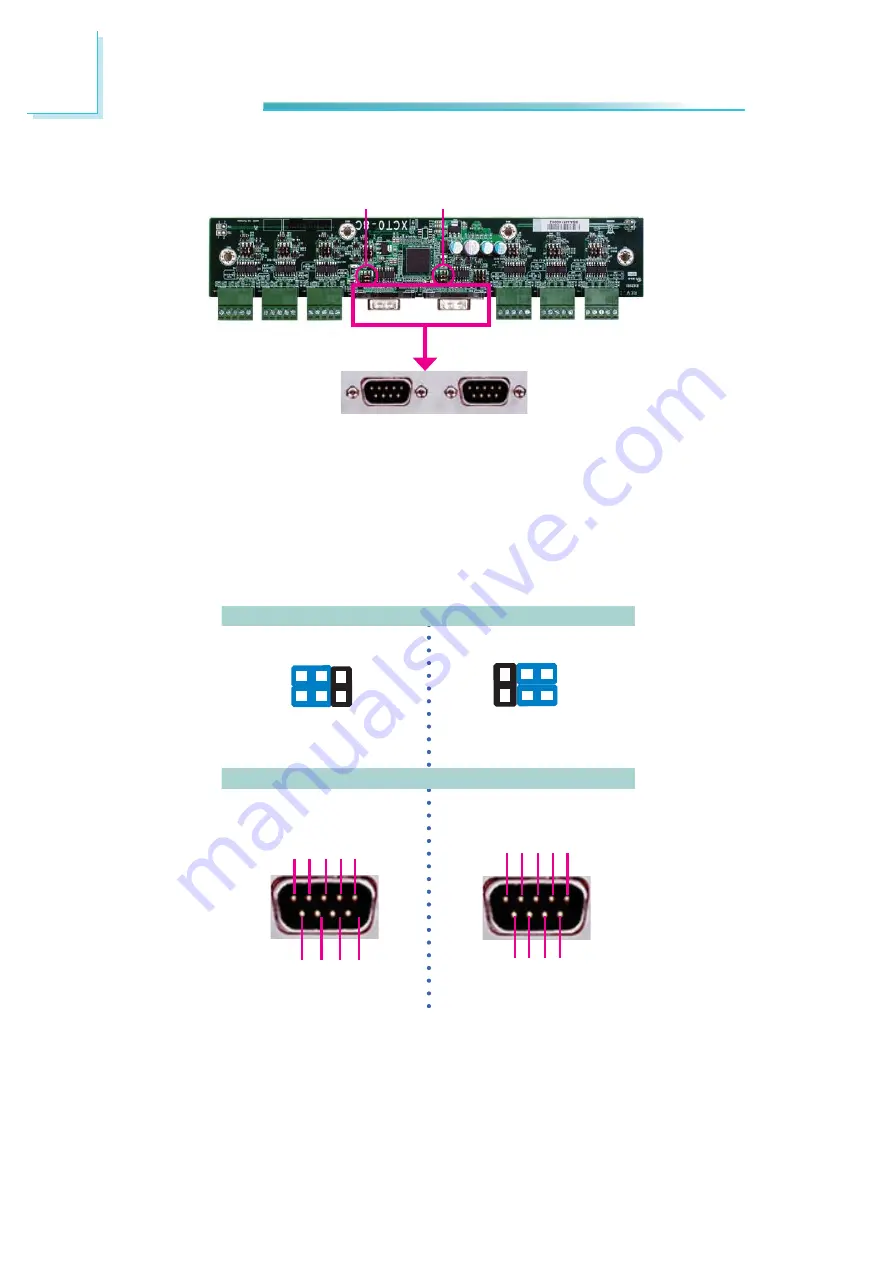
COM 6 and COM 7 RS232/Power Select
JP9 and JP10 are used to con
fi
gure COM 6 and COM 7 to pure RS232 or RS232
with power.
The pin function of COM 6 and COM 7 will vary according to JP9’s and JP10’s set-
ting respectively.
JP9 / JP10
COM 6 / COM 7
COM 6
(JP9)
COM 7
(JP10)
JP10
JP9
1-3, 2-4 On:
RS232 (default)
6
4
2
5
3
1
3-5(+12V), 4-6(+5V) On:
RS232 with power
6
4
2
5
3
1
DCD
TXD
RXD
DT
R
GND
1 2 3 4 5
6
8 9
7
DSR
CT
S
RT
S
RI
+5V
TD
RD
DT
R
-
GND
1 2 3 4 5
RT
S
-
+12V
DSR
-
CT
S-
6 7 8 9
Содержание EC300 Series
Страница 1: ...EC300 310 320 321 322 Series User s Manual A 221 M 2008 ...
Страница 12: ...1 12 Introduction EC310 Series EC310 CR6881 EC310 CR6G60 EC310 CRA060 EC310 CR4866 ...
Страница 13: ...1 13 Introduction EC320 321 322 Series EC320 321 322 CR6881 EC320 321 322 CR6G60 EC320 321 322 CRA060 ...
Страница 14: ...1 14 Introduction EC321 322 CR4G65 EC320 321 322 CR4866 ...
Страница 41: ...3 41 Installing Devices SATA power data connector SATA data connector SATA power connector ...
Страница 62: ...62 4 Jumper Settings V G A Factory Testing 2 3 On Impedance 1 3 2 1 2 On Impedance 75Ω default JP15 1 3 2 ...
Страница 117: ...6 117 Mounting Options 357 10 40 00 80 00 120 00 16 00 Ø8 50 R2 00 R2 50 ...
Страница 159: ...159 8 Supported Software 3 Click Exit ...
Страница 169: ...169 8 Supported Software 4 Click Finish ...
Страница 171: ...171 8 Supported Software 4 Click Install to begin the installation 5 After completing installa tion click Finish ...
Страница 177: ...177 8 Supported Software 7 Click Install 8 The setup program is cur rently installing the driver 9 Click Finish ...
Страница 182: ...182 8 Supported Software 4 After completing instal lation click Finish to exit setup ...


