DFI DT122-HD Скачать руководство пользователя страница 42

42

Chapter 7 BIOS Setup

Chapter 7

www.dfi .com

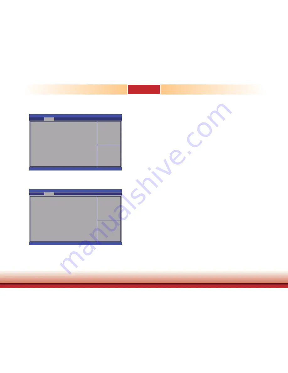
Network Stack

Enable or disable UEFI 
network stack.

Aptio Setup Utility - Copyright (C) 2012 American Megatrends, Inc.

Version 2.15.1236. Copyright (C) 2012 American Megatrends, Inc.


Network Stack

Advanced

[Enabled]


Network Stack

Enables or disables UEFI network stack.

Enable or disable UEFI 
network stack.

Aptio Setup Utility - Copyright (C) 2012 American Megatrends, Inc.

Version 2.15.1236. Copyright (C) 2012 American Megatrends, Inc.


Network Stack


Ipv4 PXE Support

    Ipv6 PXE Support
  

Advanced

[Enabled]

[Enabled]
[Enabled]

Ipv4 PXE Support

When enabled, Ipv4 PXE boot supports. When disabled, Ipv4 PXE boot option will not 

be created.

Ipv6 PXE Support

When enabled, Ipv6 PXE boot supports. When disabled, Ipv6 PXE boot option will not 

be created.



 Select Screen



   Select Item

Enter: Select
+/-:   Change Opt.
F1:   General Help
F2: Previous 

Values

F3: Optimized 

Defaults

F4:   Save & Reset  
ESC:  Exit



 Select Screen



   Select Item

Enter: Select
+/-:   Change Opt.
F1:   General Help
F2: Previous 

Values

F3: Optimized 

Defaults

F4:   Save & Reset  
ESC:  Exit

Содержание DT122-HD

Страница 1: ...1 Chapter 1 Introduction www dfi com DT122 HD Desktop Box PC User s Manual A36300541...

Страница 2: ...owners FCC and DOC Statement on Class A This equipment has been tested and found to comply with the limits for a Class A digital device pursuant to Part 15 of the FCC rules These limits are designed t...

Страница 3: ...nal Select 19 LCD Inverter Power Select 19 Panel Power Select 20 LVDS Channel and bpp Select 20 Digital I O Power Select 21 Digital I O Output State 21 Chapter 5 Ports and Connectors 22 Rear Panel I O...

Страница 4: ...gns of physical damage You must take extra care in han dling them to ensure against electrostatic build up 1 To prevent electrostatic build up leave the system board in its anti static bag until you a...

Страница 5: ...er cord Danger of explosion if battery incorrectly replaced Replace only with the same or equivalent type recommend by the manufacturer Dispose of used batteries according to local ordinance Keep this...

Страница 6: ...Overview Key Features Model Name DT122 HD Processor 4th Generation Intel CoreTM processors Chipset Intel H81 Express chipset LAN 2 LAN ports COM 2 COM ports Displays 1 HDMI 1 DVI I USB 4 USB 2 0 port...

Страница 7: ...Hz 35W Intel CoreTM i5 4570S 6M Cache up to 3 6 GHz 65W Intel CoreTM i5 4570TE 4M Cache up to 3 3 GHz 35W Intel CoreTM i3 4360 4M Cache 3 7 GHz 54W Intel CoreTM i3 4350T 4M Cache 3 1 GHz 35W Intel Cor...

Страница 8: ...device COM Ports Used to connect serial devices USB Ports Used to connect USB 3 0 2 0 1 1 devices LAN Ports Used to connect the system to a local area network Line out Used to connect to a speaker Lin...

Страница 9: ...Dimensions Front View Right View Left View Rear View 300 00 74 00 78 00 217 20 0 00 0 00 46 97 124 47 49 47 154 94 140 94 153 29 10 16 159 84 18 23 45 88 83 42 111 09 132 42 151 76 157 48 22 86 39 32...

Страница 10: ...stem 2 After the memory test the message Press DEL to run setup will appear on the screen Press the Delete key to enter the AMI BIOS setup utility Installing the Operating System Most operating system...

Страница 11: ...es 3 The 4 mounting screws on the sides of the system are used to secure the cover to the chassis Remove these screws and then put them in a safe place for later use Mounting screw Mounting screw 4 Af...

Страница 12: ...HDD brackets to the drive bay Mounting screw Mounting screw Mounting screw Drive bay Drive bay 3 Align the mounting holes of the SATA drive with the mounting holes on the HDD bracket and then use the...

Страница 13: ...drive with HDD bracket onto the drive bay Mounting screw Drive bay Mounting screw 5 Place the SATA drive bay assembly into the chassis Secure the SATA drive bay with the mounting screws you removed i...

Страница 14: ...ce the drive bay into the chassis Secure the drive bay with the mounting screws you removed in step 1 Mounting screw Drive bay Mounting screw Mounting screw Mounting screw 6 Connect the SATA data cabl...

Страница 15: ...bracket Mounting screw Bracket PCIe x16 slot Mounting bracket and mounting screw PCI slot 1 The PCIe x16 on the motherboard is used to insert a TS200 1P or TS200 1E riser card To install the expansion...

Страница 16: ...Ie x16 slot that is on the riser card Replace the screw you removed in step 1 to secure the bracket in place Mounting bracket and mounting screw PCI Bracket Expansion card Rear view Note The Expansion...

Страница 17: ..._standby 1 2 On 5V default 3 1 2 3 1 2 If you encounter the followings a CMOS data becomes corrupted b You forgot the supervisor or user password you can reconfigure the system with the default values...

Страница 18: ...2A Power on Select 1 2 On Power on via power button default 2 3 On Power on via AC power USB 4 5 JP6 2 3 On 5V_standby 1 2 On 5V default JP10 is used to select the method of powering on the system If...

Страница 19: ...ct JP12 2 5 8 11 3 6 9 12 On mSATA 1 4 7 10 2 5 8 11 On PCIe default 12 10 3 1 JP12 is used to select the Mini PCIe signal 12 10 3 1 LCD Inverter Power Select 1 2 On 12V 2 3 On 5V default 3 1 2 3 1 2...

Страница 20: ...e powering on the system make sure that the power settings of JP11 match the LCD panel s specification Selecting the incorrect voltage will seriously damage the LCD panel LVDS Channel and bpp Select S...

Страница 21: ...of DIO Digital I O signal Based on the power level of DIO Digital I O selected on JP15 JP16 DIO pin 0 3 and JP17 DIO pin 4 7 are used to select the output state of Digital I O pull high or pull low Wh...

Страница 22: ...yboard Mouse The Wake On PS 2 Keyboard Mouse function allows you to use the PS 2 keyboard or PS 2 mouse to power on the system To use this function Jumper Setting JP1 must be set to 2 3 On 5V_standby...

Страница 23: ...stem board is equipped with two onboard USB 3 0 ports USB 0 1 and four onboard USB 2 0 ports USB 4 5 10 11 The 10 pin connector allows you to connect 2 additional USB 2 0 1 1 ports USB 2 3 The additio...

Страница 24: ...st be set to 2 3 On 5V_standby Refer to USB Power Select in this chapter for more information HDMI Port The HDMI port which carries both digital audio and video signals is used to connect a LCD monito...

Страница 25: ...formation Front audio 1 Mic2 L Line2 R Front_IO_Sense GND Presence Signal Key 2 10 Mic2 JD Line2 JD 9 Mic2 R Line2 L COM 1 and COM 2 are fixed at RS232 The serial ports are asynchronous communication...

Страница 26: ...enu of the BIOS Refer to the chapter 7 for more information Features The 8 bit Digital I O connector provides powering on function to external devices that are con nected to these connectors 1 4 12V G...

Страница 27: ...to the processor s Voltage Regulator Module VRM The power connectors from the power supply unit are designed to fit the 24 pin and 4 pin connectors in only one orientation Make sure to find the proper...

Страница 28: ...tion 2 1 LVDS LCD panel 40 39 Pins Function Pins Function 1 GND 2 GND 3 LVDS_Out3 4 LVDS_Out7 5 LVDS_Out3 6 LVDS_Out7 7 GND 8 GND 9 LVDS_Out2 10 LVDS_Out6 11 LVDS_Out2 12 LVDS_Out6 13 GND 14 GND 15 LV...

Страница 29: ...PWR LED ATX SW 12 11 2 1 Front Panel HDD LED HDD LED This LED will light when the hard drive is being accessed RESET SW Reset Switch This switch allows you to reboot without having to power off the s...

Страница 30: ...vices Failure to do so will cause severe damage to the motherboard and components S PDIF Connector The S PDIF connector is used to connect an external S PDIF port Your S PDIF port may be mounted on a...

Страница 31: ...automatically hold the graphics card in place Mini PCI Express Slot The Mini PCIe socket is used to install a Mini PCIe card Mini PCIe card is a small form factor PCI card with the same signal protoco...

Страница 32: ...system please remove them first Mounting screw Mounting screw 2 At the sides of the system use the mounting screws removed in step 1 to secure the wall mount brackets on each side of the system Mount...

Страница 33: ...The 4 mounting holes on the sides of the system are used to mount the type B wall mount bracket 2 Use the provided mounting screws to secure the type B wall mount brackets on each side of the system...

Страница 34: ...u power up the system the BIOS message appears on the screen and the memory count begins After the memory test the message Press DEL to run setup will appear on the screen If the message disappears be...

Страница 35: ...language Aptio Setup Utility Copyright C 2012 American Megatrends Inc Save Exit Chipset Version 2 15 1236 Copyright C 2012 American Megatrends Inc Select Screen Select Item Enter Select Change Opt F1...

Страница 36: ...ct Change Opt F1 General Help F2 Previous Values F3 Optimized Defaults F4 Save Reset ESC Exit Trusted Computing This section configures settings relevant to Trusted Computing innovations Aptio Setup U...

Страница 37: ...Processor Family Microcode Patch FSB Speed Max CPU Speed Min CPU Speed CPU Speed Processor Cores Intel HT Technology Intel VT X Technology Intel SMX Technology 64 bit EIST Technology CPU C3 State CPU...

Страница 38: ...ontroller Speed Indicates the maximum speed that the SATA controller can support Port 0 Port 1 and Port 4 Enables or disables the SATA port Hot Plug Designates the SATA port as hot pluggable When IDE...

Страница 39: ...ff This is a workaround for OSes without XHCI hand off support The XHCI ownership change should be claimed by XHCI driver EHCI Hand off This is a workaround for OSes that does not support EHCI hand of...

Страница 40: ...Advanced Enabled IO 2F8h IRQ 3 Auto Select Screen Select Item Enter Select Change Opt F1 General Help F2 Previous Values F3 Optimized Defaults F4 Save Reset ESC Exit Restore AC Power Loss Power Off W...

Страница 41: ...Fan Function CPU Smart Fan Control Boundary 4 Boundary 3 Boundary 2 Boundary 1 Speed Count 5 Speed Count 4 Speed Count 3 Speed Count 2 Speed Count 1 System Smart Fan Control Boundary 4 Boundary 3 Boun...

Страница 42: ...2 15 1236 Copyright C 2012 American Megatrends Inc Network Stack Ipv4 PXE Support Ipv6 PXE Support Advanced Enabled Enabled Enabled Ipv4 PXE Support When enabled Ipv4 PXE boot supports When disabled I...

Страница 43: ...reference This section is used to configure the parameters of Gigabit Ethernet device Click to configure the network device port Aptio Setup Utility Copyright C 2012 American Megatrends Inc Version 2...

Страница 44: ...oots it will first initialize the onboard VGA PEG When the system boots it will first initialize the PCI Express x16 graphics card Internal Graphics Keeps IGD enabled based on the setup options Graphi...

Страница 45: ...POST This has no effect if external graphics present Secondary boot display selection will appear based on your selection VGA modes will be sup ported only on primary display Aptio Setup Utility Copyr...

Страница 46: ...15 1236 Copyright C 2012 American Megatrends Inc Memory Information Memory RC Version Memory Frequency Total Memory Memory Voltage DIMM 1 DIMM 2 CAS Latency tCL Minimum delay time CAS to RAS tRCDmin R...

Страница 47: ...xpress Configuration This field is used to configure the PCI Express settings PCI Express Root Port 1 Settings Aptio Setup Utility Copyright C 2012 American Megatrends Inc Version 2 15 1236 Copyright...

Страница 48: ...bled and Disabled When Disabled is selected in the XHCI Mode it will display the following information EHCI 1 and EHCI 2 These fields are used to control the functions of USB EHCI USB 2 0 controllers...

Страница 49: ...led Enabled Enabled Enabled Enabled Chipset USB Port 0 1 2 3 4 5 8 10 11 Enables or disables these USB ports Control detection of the Azalia device Disable Azalia will be unconditionally disabled Enab...

Страница 50: ...isabled CSM Parameters This option controls if CSM will be launched Aptio Setup Utility Copyright C 2012 American Megatrends Inc Version 2 15 1236 Copyright C 2012 American Megatrends Inc Launch CSM B...

Страница 51: ...Utility Copyright C 2012 American Megatrends Inc Version 2 15 1236 Copyright C 2012 American Megatrends Inc Save Changes and Reset Discard Changes and Reset Restore Defaults Boot Override Chipset Adv...

Страница 52: ...lready been integrated into this system board Due to the safety concerns the BIOS SPI ROM chip cannot be removed from this system board and used on another system board of the same model 2 The BIOS SP...

Страница 53: ...ations required to enhance the performance of the system board Insert the CD into a CD ROM drive The autorun screen Mainboard Utility CD will appear If after inserting the CD Autorun did not automatic...

Страница 54: ...files so that the Intel chipset can be recognized and configured properly in the system To install the utility click Intel Chipset Software Installation Utility on the main menu 1 Setup is ready to in...

Страница 55: ...and the system rebooted the screen will turn blank for 1 to 2 minutes while WinSAT is running before the Windows Vista desktop appears The blank screen period is the time Windows is testing the graph...

Страница 56: ...l the driver click Intel Management Engine Drivers on the main menu 1 Setup is ready to install the driver Click Next 2 Read the license agreement then click Yes 3 Setup is currently installing the dr...

Страница 57: ...Restarting the system will allow the new software installation to take effect 1 Setup is ready to install the driver Click Next Intel LAN Drivers To install the driver click Intel LAN Drivers on the m...

Страница 58: ...tallation 5 After completing installa tion click Finish NuvSerial To install the driver click NuvSerial on the main menu 1 The setup program is preparing to install the driver 2 The setup program is n...

Страница 59: ...tus 5 Click Finish to exit the wizard after the installation is completed Intel USB 3 0 Drivers For Windows 7 To install the driver click Intel USB 3 0 Driver on the main menu 2 Read the license agree...

Страница 60: ...completing installation click Finish Intel Rapid Storage Technology The Intel Rapid Storage Technology is a utility that allows you to monitor the current status of the SATA drives It enables enhance...

Страница 61: ...requirements and instal lation tips then click Next 5 Setup is now installing the utility Click Next to continue 3 Read the license agreement then click Yes 6 Click Yes I want to restart my computer n...

Страница 62: ...Adobe Acrobat Reader 9 3 To install the reader click Adobe Acrobat Reader 9 3 on the main menu 1 Click Next to install or click Change Destination Folder to select another folder 2 Click Install to be...

Страница 63: ...reads from this register reflect the value that is in the flip flop contolling the output selection not the actual pin value BIT O 7 O 6 O 5 O 4 O 3 O 2 O 1 O 0 DEFAULT 1 1 1 1 1 1 1 1 Register 0 Inp...

Страница 64: ...Data if Mode 1 SetBit Data TempPinNum Input else ClrBit Data TempPinNum Output I2C_WriteByte SLAVE_ADDR CONFIG_PORT Data return 1 GPIO Output Process define SLAVE_ADDR define INPUT_PORT define OUTPUT_...

Страница 65: ...WDT Control WDT timer MOV DX 4EH MOV AL 07H Ready to Program Logical Device OUT DX AL MOV DX 4FH MOV AL 08H Select Logical Device 8 OUT DX AL MOV DX 4EH MOV AL F1H Select watchdog timer register OUT...

Страница 66: ...which setting is correct either turn off the system and change the jumper or enter Setup and change the VIDEO selection FLOPPY DISK S fail 80 Unable to reset floppy subsystem FLOPPY DISK S fail 40 Fl...

Страница 67: ...at the video input cable is properly attached to the monitor and the system s dis play adapter 4 Adjust the brightness of the display by turning the monitor s brightness control knob The picture seems...

Страница 68: ...ks by attaching it to a serial port that is working and configured correctly If the serial device does not work either the cable or the serial device has a problem If the serial device works the probl...

Отзывы: