www.dfi .com
19
Chapter 2 Hardware Installation
Chapter 2
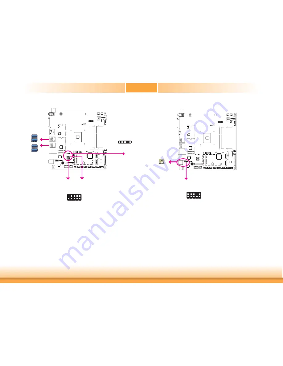
USB Ports
USB 1
USB 0
USB 2
USB 3.0
2
10
VCC
-Data0
+Data0
GND
VCC
-Data1
+Data1
GND
NC
9
1
2
USB 2.0
USB 6-7
USB 8 or optional
vertical USB
1
5
GND
-Data0 +Data0
VCC
USB 4
USB 4-5
The USB device allows data exchange between your computer and a wide range of simultane-
ously accessible external Plug and Play peripherals.
The system board is equipped with four onboard USB 3.0 ports (USB 0-1/2-4) at the rear
panel I/O ports. The 10-pin connectors allow you to connect 4 additional USB 2.0 ports (USB
4-5/6-7). The 5-pin connector allows you to connect 1 additional USB 2.0 port (USB 8). The
additional USB ports may be mounted on a card-edge bracket. Install the card-edge bracket
to an available slot at the rear of the system chassis and then insert the USB port cables to a
connector.
USB 2.0
USB 3.0
Wake-On-USB Keyboard/Mouse (optional)
The Wake-On-USB Keyboard/Mouse function allows you to use a USB keyboard or USB mouse
to wake up a system from the S3 (STR - Suspend To RAM) state.
Audio
Rear Audio
The system board is equipped with 1 audio jack. This jack is a one-hole connecting interface
for inserting a plug.
• Line-out Jack (Lime)
This jack is used to connect a headphone or external speakers.
Front Audio
The front audio connector allows you to connect to the second line-out and mic-in jacks that
are at the front panel of your system.
BIOS Setting
Configure these onboard Audio devices in the Advanced menu (“Audio Configuration” sub-
menu) of the BIOS. Refer to the chapter 3 for more information.
Driver Installation
Install the audio driver. Refer to the chapter 4 for more information.
2
Front Audio
1
Mic
-L
Line-R
GND
GND NC
2
10
Mic
-J
D
Line-
JD
9
Mic
-R
Line-L
Line-out


